Rotorcraft Hydraulic Manifold Emergency Replacement: Selecting the Fastest Route to Operational Readiness
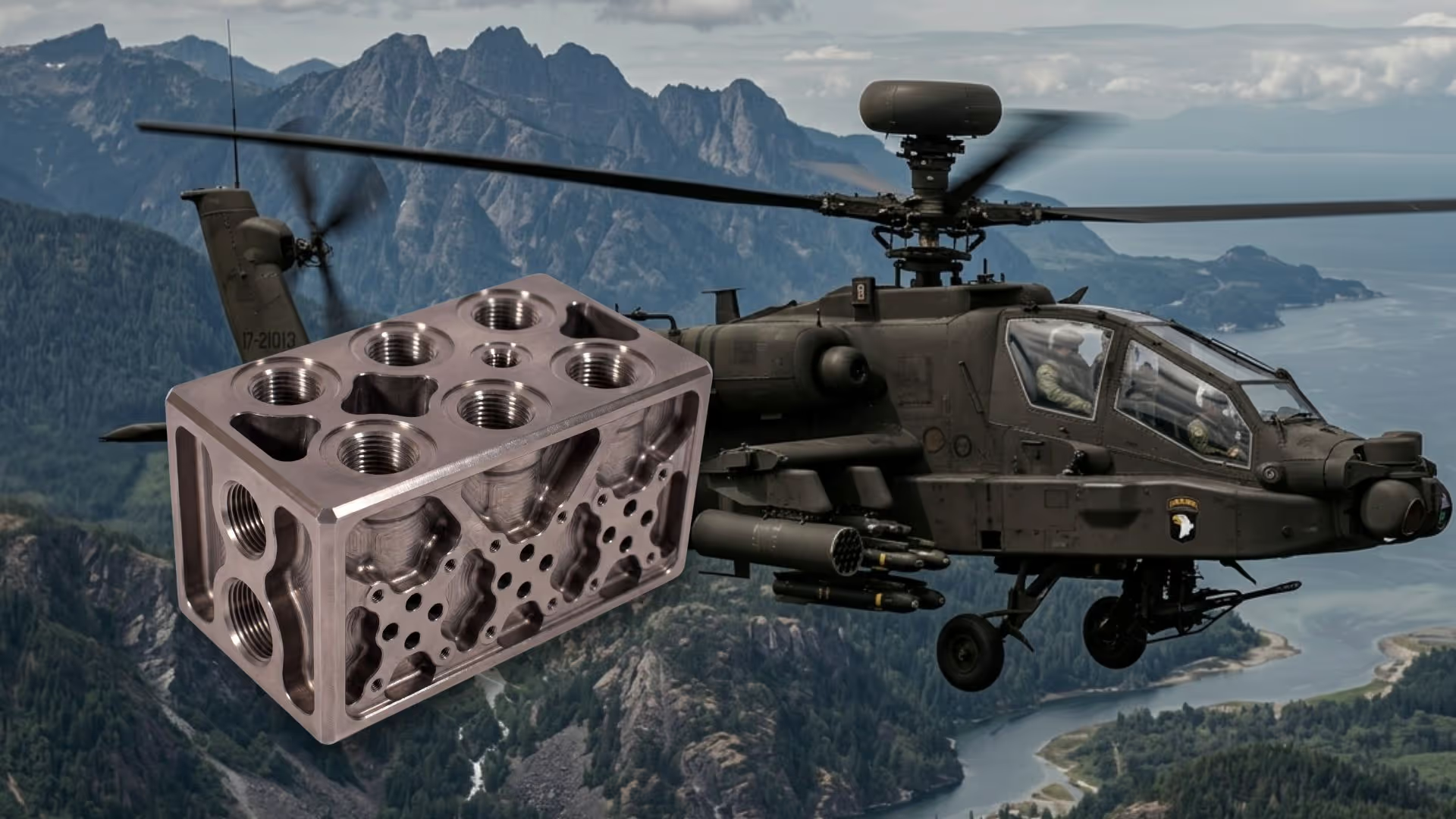
The Part
The hydraulic manifold is a primary flight-control distribution component on a military rotorcraft, routing 207 bar operating-pressure fluid from a central bore to six branch actuator circuits arranged linearly along its lower face. The legacy design was a machined Al-7075-T6 tubular body with cross-drilled branch ports, knurled port fittings at each exit, and flanged end caps for circuit entry and termination. Al-7075-T6 was selected for its high specific strength, established defense material process qualification, and compatibility with the demanding certification environment. The part must sustain sustained rotor-induced vibration and high-shock events representative of crash-hazard conditions throughout its service life.
%20-%20Copy.avif)
The Challenge
In an emergency replacement scenario, the design phase is the only lead time lever the engineering team controls directly. A conventional sequential redesign process, covering geometry iteration, external FEA, and DFM correction across two separate manufacturing route evaluations, would have consumed 9 to 12 weeks before a validated drawing existed for either option. That timeline was operationally unacceptable for a grounded fleet. Certification requirements added a further constraint: military airworthiness re-qualification demands a complete, auditable design package, and in a rushed conventional workflow that documentation is assembled retroactively, extending the review cycle independent of the engineering work itself.
The Approach
Both manufacturing routes were run from day one in parallel. Rather than evaluating CNC machining and DMLS additive manufacturing sequentially and doubling the design phase, both tracks were executed simultaneously with route-specific manufacturing constraints and concurrent multi-physics load cases applied from the first generation pass. This compressed the route selection decision from a multi-week sequential process into a single comparative output from one design exploration cycle.
The route that delivered the fastest path to operational readiness was not the one that initial intuition favored for a complex hydraulic geometry. The case study details the constraint architecture that drove each manufacturing track, the wall correction findings that emerged from concurrent FEA, and the full comparative lead time breakdown that determined the final route selection.
Key Results
- Engineering lead time cut from 10-12 weeks to 3 weeks, across two manufacturing routes evaluated simultaneously in a single design cycle
- Total lead time to shipment reduced to 7-8 weeks, vs. an estimated 20-25 weeks with a conventional sequential process, a 3x compression across the full design-to-delivery cycle
- 20+ variants generated across both manufacturing routes in parallel, vs. 2-3 concepts per route in a conventional sequential workflow
Why It Matters
When supply chain failure grounds an operational fleet, the design phase is the only timeline variable the engineering team controls. Running manufacturing route evaluation in parallel with multi-physics simulation, rather than sequentially, compresses that window without compromising the certification traceability required for airworthiness re-qualification. This pattern applies to any regulated sector where a documented, auditable design package is a precondition for part release.
Download the case study to see the route-by-route manufacturing constraint comparison, the complete structural metrics table, and the third-party FEA validation data for both the CNC and DMLS candidates.

Interested in reading the full case study?
Fill in the form below to instantly receive the full case study.
Aeronautics Challenges We Address



FAQs
Explore our frequently asked questions to understand how our software can benefit you.
Conventional workflows evaluate CNC machining and additive manufacturing routes sequentially, requiring DFM corrections and FEA validation for one route before the other can begin. This doubles the design phase before any route decision exists. Running both tracks simultaneously, with route-specific constraints applied from the first generation pass, compresses the comparison into a single design cycle. For a hydraulic manifold emergency replacement, this can lead to an engineering lead time reduction from an estimated 9-12 weeks to 3 weeks.
A primary flight-control hydraulic manifold on a military rotorcraft must withstand three concurrent load conditions: internal proof pressure operating pressure, sustained rotor-induced vibration, and high-shock events representative of crash-hazard conditions. Each load case produces distinct failure modes, and a complete validation package must address all three simultaneously to satisfy military airworthiness re-qualification requirements. Safety factors above 2.0 on structural yield and above 1.5 on burst pressure are typical acceptance thresholds in this class of application.
Cognitive Design generates a complete, auditable record linking each geometric decision to its load case input, manufacturing constraint set, and validated FEA output. This traceability is built during the design exploration process itself, not assembled retroactively. For military airworthiness re-qualification, a complete design package with documented decision rationale reduces the certification review cycle by eliminating documentation gaps that typically extend review timelines independent of the underlying engineering work.
Automotive Challenges We Address



Defense Challenges We Address


Built for the Cognitive Era of Engineering
Shorten product development cycle from the earliest concept phase.
Product engineering cycle
Product engineering cycle
Reusability of engineering workflows
Unlock Your Design Potential
Request a demo to see how Cognitive Design by CDS can revolutionize your engineering workflow