Wing Rib Family Lightweighting and Manufacturing Route Selection for a Regional Turboprop Aircraft

The Part
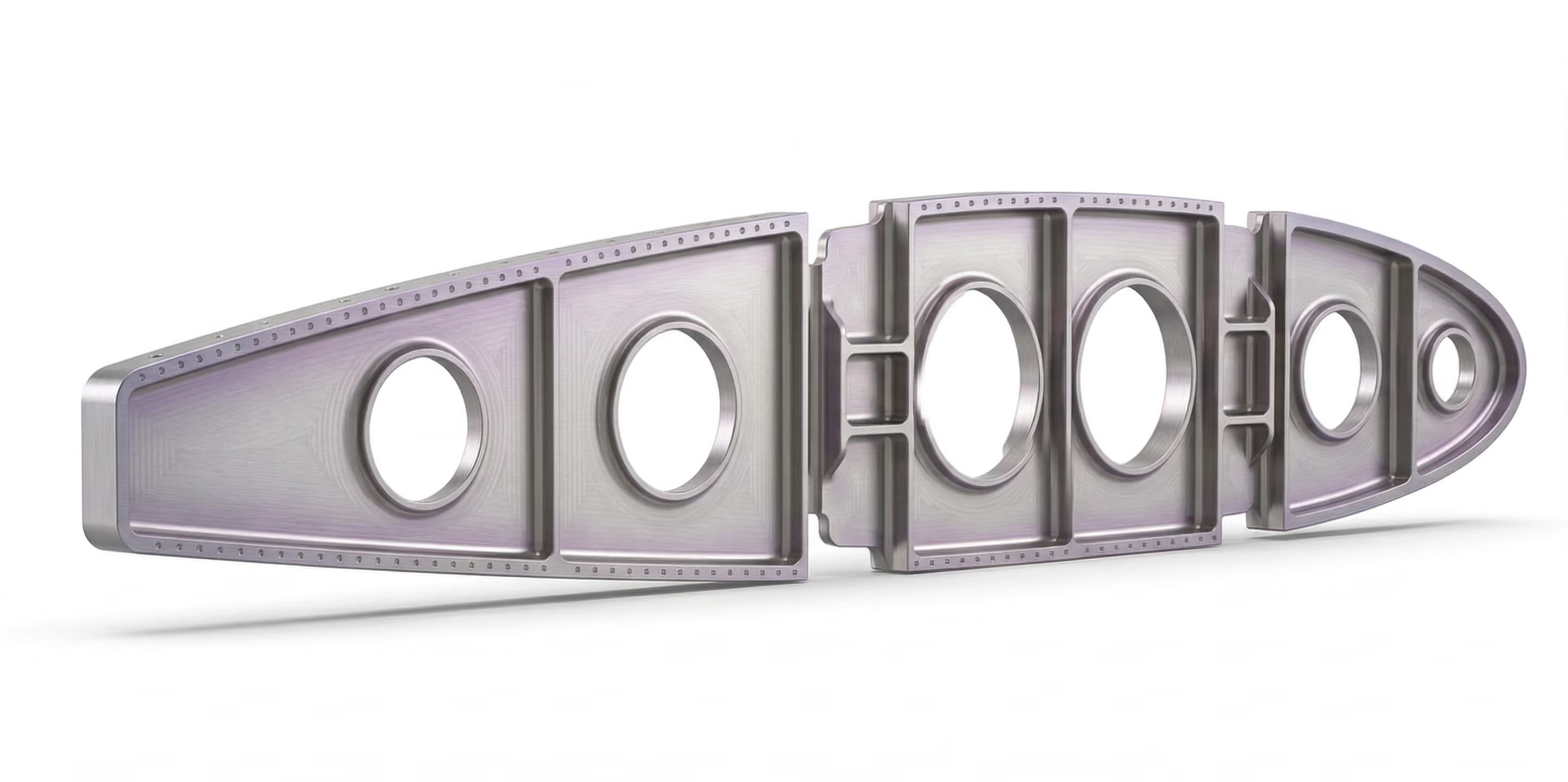
The wing rib is a primary structural member across a five-position span variant family on a regional turboprop aircraft, transferring aerodynamic and ground loads from the skin panels into the wing box while accommodating fuel-system interfaces and inspection access. Each variant carries a different chord length, rib height, and local load intensity, all governed by CS-25 limit and ultimate load requirements, plus gust and landing impact cases. Al-7075-T6 was selected over the Al-2024-T3 baseline for its higher yield strength (503 MPa versus 345 MPa), giving the team margin to remove mass while still meeting the full structural load envelope.
The Challenge
The legacy ribs were not failing. Each variant had flown for years within a safety factor of 2.8, well above the CS-25 requirement. The pressure driving redesign was scale, not performance. Exploring five span positions independently under a conventional workflow means rebuilding geometry, meshing, and manufacturability review for each one in sequence, turning a single-rib study into months of non-recurring engineering.
A second constraint compounded the first: draft angles, split lines, and tool-access envelopes for the two candidate manufacturing routes, die casting and 5-axis machining, are typically checked only once a structural concept is already committed, forcing rework late in the program.
The Approach
The team ran a Design of Experiments across the full design space, generating 50+ variants in a single parallel pass instead of the 2 to 3 concepts a sequential workflow allows in the same window. Manufacturing constraints for both die casting and 5-axis machining were embedded from the first iteration, so every ranked candidate was already producible.
The manufacturing route the data pointed to was not the default assumption: die casting won out over machining once production volume and cost-per-part at scale were factored in, not on structural grounds alone. Once the mid-span rib was validated, the full workflow, including topology optimization, MDD constraints, and SDD refinement, was converted into a reusable parametric template.
The case study details the full DoE configuration, the load case setup under CS-25 gust and landing conditions, and the parametric template architecture that regenerated the remaining four rib positions automatically.
Key Results
- 28% mass reduction per rib position, from 3.15 kg to 2.27 kg (estimated), fully CS-25 compliant
- 50+ design candidates explored in parallel, versus 2-3 in a conventional sequential workflow
- 2 days per variant after initial workflow buildup, down from 2 weeks, a 3x reduction across the full 5-rib family
The case study includes the complete before/after metrics table, validation data, and the parametric template architecture used to regenerate the remaining rib positions.
Why It Matters
When manufacturability and structural optimization run together from the first iteration, comparing manufacturing routes stops being a late-stage check and becomes part of the design decision itself. For part families sized like this one, the reusable workflow is what turns a five-variant program into a single engineering investment rather than five separate ones.
Download the case study to see the complete metrics table, the full CS-25 load case validation data, and the parametric template architecture.

Interested in reading the full case study?
Fill in the form below to instantly receive the full case study.
Aeronautics Challenges We Address



FAQs
Explore our frequently asked questions to understand how our software can benefit you.
It works for all three process families, provided the constraints specific to each are built into the exploration phase from the start: overhang angle for additive, draft angle for casting, tool accessibility for machining.
Yes, provided the design process is documented and traceable, and the final geometry is revalidated using the qualification methods applicable to the relevant sector. The complexity usually lies less in the calculation itself than in the compliance documentation that accompanies it.
Once the reference variant is validated and converted into a reusable parametric workflow, downstream variants typically regenerate through the same topology optimization, MDD, and SDD chain with only the input geometry and load magnitude updated. In a documented five-position wing rib family, this reduced per-variant engineering lead time from 2 weeks to 2 days after the initial workflow buildup, cutting the full family's engineering time from roughly 10 weeks to about 3.5 weeks.
Legacy parts are often dimensioned with a wide margin above the applicable structural requirement, simply because the original design process could not explore enough alternatives to converge on the load envelope precisely. When a part is re-optimized against the full CS-25 load case set and validated with final FEA, the resulting safety factor can land much closer to the compliance threshold, for example 1.5 versus a legacy 2.8, while still meeting every ultimate load and structural requirement.
Automotive Challenges We Address



Defense Challenges We Address


Built for the Cognitive Era of Engineering
Shorten product development cycle from the earliest concept phase.
Product engineering cycle
Product engineering cycle
Reusability of engineering workflows
Unlock Your Design Potential
Request a demo to see how Cognitive Design by CDS can revolutionize your engineering workflow