Implicit Modeling vs. B-Rep: A Technical Comparison for Modern Mechanical Engineering

Rhushik Matroja
Rhushik Matroja
CEO
January 27, 2026
10
min read
Share this post
Implicit Modeling vs. B-Rep: A Technical Comparison for Modern Mechanical Engineering

For decades, boundary representation (B-rep) has served as the unquestioned foundation of computer-aided design, enabling engineers to translate conceptual sketches into manufacturable geometry with unprecedented precision. Yet as these industry leaders pursue aggressive lightweighting targets and the geometric complexity enabled by advanced manufacturing, the limitations of explicit surface-based modeling have become impossible to ignore and increasingly costly to work around.

This technical comparison examines the fundamental differences between B-rep and implicit modeling to equip design engineers with the knowledge required to select the optimal approach for each phase of the product development cycle.

The Geometry Paradigm Shift in Mechanical Design

The dominance of boundary representation in mechanical CAD emerged during the 1980s, when computational resources demanded efficient mathematical descriptions of solid geometry. B-rep's elegant approach of defining solids through the vertices, edges, and faces that form their boundaries proved remarkably well-suited to the prismatic geometries characteristic of machined and cast components. Major CAD platforms built their modeling engines on this foundation, creating an ecosystem of interoperable tools that has served global manufacturing for four decades.

The paradigm began to shift with the convergence of four technological forces that leading manufacturers could no longer address with traditional tools:

  • Topology optimization maturity: Algorithms became capable of generating organic, stress-optimized structures promising significant weight reduction, but produced geometries that B-rep systems struggled to represent and manipulate effectively.
  • Simulation-driven design integration: Workflows demanded tighter coupling between analysis and geometry creation to accelerate development cycles, yet B-rep reconstruction from simulation results remained a frustrating manual bottleneck.
  • Manufacturing-driven design philosophy: Early-stage evaluation of production feasibility became essential to eliminate costly late-stage iterations, requiring geometry representations that could embed manufacturing constraints natively from the first concept.

Each of these forces exposed fundamental limitations in B-rep's ability to represent, manipulate, and iterate upon the complex geometries modern engineering demands. The response from forward-thinking organizations has been to adopt implicit geometry engine that extends the engineer's design space into domains where surface-based representations struggle: design exploration, optimized models, and any geometry requiring robust Boolean operations at scale.

Understanding B-Rep: The Legacy Standard

How Boundary Representation Works

Boundary representation encodes solid geometry by explicitly describing the surfaces that enclose a volume. B-rep maintains a topological data structure comprising vertices, edges, and faces, with each face carrying geometric data such as NURBS surfaces for complex curvature or analytic forms for prismatic features. The structure tracks topological relationships, enabling precise model interrogation for distance calculations, interference detection, and mass property analysis.

Illustration of a B-Rep model

Industry-standard formats including STEP and IGES serialize B-rep data for interoperability across the CAD/CAM/CAE ecosystem. This interoperability represents B-rep's most significant advantage: models flow through PLM, CAM, and CMM workflows with high fidelity.

Boundary representation encodes solid geometry by explicitly describing the surfaces that enclose a volume. B-rep maintains a topological data structure comprising vertices, edges, and faces, with each face carrying geometric data such as NURBS surfaces for complex curvature or analytic forms for prismatic features.

Strengths and Limitations in Production Workflows

The precision of B-rep geometry directly supports production engineering requirements that companies depend upon daily. Tolerancing and geometric dimensioning and control (GD&T) annotations attach naturally to explicit surfaces, edges, and datums. CAM systems generate toolpaths by offsetting from B-rep surfaces, calculating cutter-contact points with mathematical exactness. Quality assurance workflows compare measured point clouds against nominal B-rep geometry to verify dimensional conformance.

However, the very explicitness that makes B-rep powerful for production becomes a significant liability during concept exploration. Boolean operations, the fundamental unions, intersections, and subtractions that combine geometric primitives, exhibit fragility when applied to complex or near-coincident geometry. Experienced CAD users recognize the frustration of failed fillets, non-manifold edges, and operations that simply refuse to compute when surface intersections approach numerical tolerance limits.

These failures become endemic when working with intricate results. Optimization algorithms produce density fields indicating where material should exist; converting these fields into manufacturable B-rep geometry requires extensive manual reconstruction involving smoothing iso-surfaces, filling holes, adding fillets, and resolving surface errors. Industry estimates suggest that this reconstruction phase can consume 40 to 60 percent of total topology optimization project time.

Understanding Implicit Modeling: The Functional Approach

The Mathematical Foundation of Implicit Geometry

Implicit modeling represents a fundamental departure from surface-based thinking. An implicit geometry engine defines solids through scalar field functions (F-Rep)assigning a signed value to every point in three-dimensional space. Points inside carry negative values; points outside carry positive values; the boundary exists as the zero-level set where the function equals zero. Signed distance fields (SDFs), where values represent shortest distance to the boundary, are the most common implementation.

Illustration of Implicit Modeling Representation

This volumetric representation fundamentally changes how geometric operations execute. Boolean unions become minimum operations on underlying fields; intersections become maximum operations. Offsetting, notoriously failure-prone in B-rep systems, reduces to adding a constant to field values. These operations never fail because they operate on continuous mathematical functions rather than discrete topological structures.

Implicit modeling represents a fundamental departure from surface-based thinking. An implicit geometry engine defines solids through scalar field functions assigning a signed value to every point in three-dimensional space.

Why Implicit Modeling Excels in Generative Workflows

The native affinity between implicit modeling and generative design workflows derives from a shared mathematical foundation that enables true parametric exploration of the design space. Topology optimization algorithms inherently produce implicit representations: the density field indicating optimal material distribution is itself a scalar field from which geometry can be extracted directly. Rather than converting optimization results to B-rep and suffering the attendant reconstruction burden, implicit modeling preserve the native representation throughout the design process.

This preservation unlocks capabilities impossible in B-rep environments. Field-driven parametric design allows geometric parameters such as wall thickness, lattice beam diameter, and surface texture depth to vary continuously according to simulation results. A structural component can feature thicker walls in high-stress regions and thinner walls elsewhere, with smooth transitions rather than discrete steps.

Advantages for Conventional Manufacturing Methods

While implicit modeling's association with additive manufacturing dominates industry discussion, its advantages extend equally to conventional manufacturing methods to operate at scale.

  • Casting applications benefit substantially from implicit geometry's smooth blending operations. Draft angles required for pattern extraction apply as continuous field modifications rather than discrete surface operations. Minimum wall thickness constraints, critical for ensuring complete mold filling, evaluate directly on the implicit representation. Undercut detection becomes straightforward field analysis. Complex fillet transitions between intersecting ribs, notorious for causing B-rep failures, generate automatically through implicit blending.
  • Machining constraints similarly integrate into implicit concept workflows. Tool accessibility analysis, determining which surfaces a given cutter geometry can reach, operates on the implicit field to identify inaccessible pockets before committing to B-rep detailing. Minimum feature spacing, critical for avoiding tool collisions and excessive deflection, evaluates as a field-based constraint.
  • Injection molding constraints including uniform wall thickness, draft requirements, and parting line considerations integrate into early-stage implicit workflows. The field-based representation naturally supports thickness analysis, enabling engineers to identify thin-wall fill challenges before mold design begins.

The broader insight is that implicit modeling also enables manufacturing-driven design for conventional processes, not merely additive manufacturing. By evaluating manufacturability constraints during concept exploration, when design changes remain inexpensive, engineering teams avoid the iteration loops that arise when detailed designs prove infeasible to manufacture. However, most common software solutions on the market don't cover manufacturing constraints entirely, which limits the relevance of the generated results.

Advantages for Additive Manufacturing

Additive manufacturing and implicit modeling share natural compatibility that forward-thinking organizations have leveraged to achieve breakthrough results. Practitioners report implicit files of several megabytes expanding to gigabytes when converted to mesh formats, creating data management challenges that implicit workflows avoid entirely.

Design for additive manufacturing (DfAM) constraints integrate naturally into implicit workflows within an advanced concept engineering platform like Cognitive Design. Overhang angle limits, minimum feature sizes, and support structure requirements can be evaluated continuously as geometry evolves. Build orientation analysis, critical for AM success, operates efficiently on the underlying scalar field. The result is concept geometry arriving at detailed design already validated for AM feasibility, reducing late-stage redesigns and enabling true Concurrent Engineering.

Back2CAD: Conversion Considerations

Understanding the conversion landscape is essential for engineers adopting implicit modeling technologies. A critical clarification: implicit modeling itself maintains full geometric fidelity throughout the design process. The loss of parametric tree, sharp feature control involving edges, precise fillets, and exact chamfers occurs only during conversion to B-rep or mesh formats for downstream consumption, not as an inherent limitation of the implicit representation.

Modern solutions address conversion through several approaches: direct implicit-to-manufacturing pipelines bypassing conversion entirely for AM workflows; improved algorithms like Back2CAD preserving sharp features more accurately; and emerging interoperability standards enabling native implicit data exchange without intermediate conversion.

However, neither paradigm emerges as universally superior. The most effective engineering organizations master both paradigms and transition strategically through well-defined Concurrent Engineering processes.

See how you can convert implicit files into parametric STEP files in Cognitive Design:

The Hybrid Workflow: Combining Implicit and B-Rep

Concept Phase to Detailed Design

Leading aerospace and automotive suppliers leverage each paradigm's strengths in sequence. During concept exploration, implicit modeling enables rapid generation of structures and manufacturing-constrained geometries. Engineers evaluate hundreds of variants through AI-driven exploration, investigations that would be prohibitively time-consuming in B-rep environments.

Here is the updated table, applying your custom styling and layout to the comparison between B-Rep and Implicit Modeling.
Criterion B-Rep Implicit Modeling
Boolean Robustness Fragile with complex geometry Highly robust; operations never fail
Organic Geometry Difficult; requires extensive patching Native strength; smooth blending automatic
Lattices & TPMS Impractical beyond simple structures Seamless generation at any complexity
Sharp Feature Precision Excellent with explicit edge control Excellent in native form; conversion-dependent
CAM Compatibility Direct toolpath generation Requires conversion to B-rep or mesh
DFM Integration Typically post-design validation Early-stage native evaluation
File Size (Complex Parts) Large; scales with face count Compact; mathematical representation
Industry Adoption Universal across manufacturing Growing rapidly in advanced sectors

Once optimal concepts are identified, conversion to B-rep enables precise tolerancing, GD&T annotation, assembly integration, and CAM toolpath generation. The implicit phase reduces the design space; the B-rep phase finalizes production intent.

How Cognitive Design Bridges the Gap

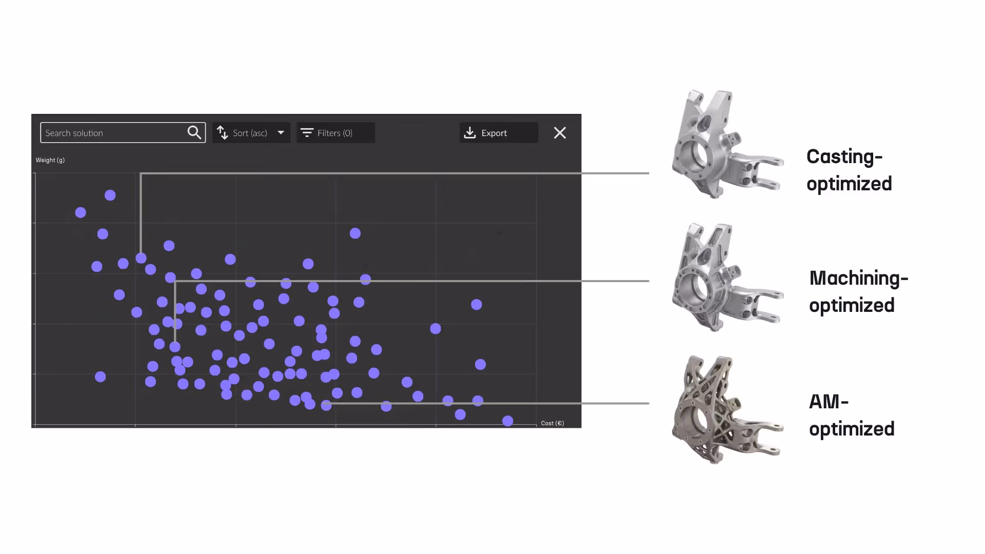
Cognitive Design exemplifies the advanced concept engineering platform approach to hybrid workflows, delivering capabilities that position it as an industry-leading solution rather than a traditional CAD software. Built on a proprietary implicit geometry engine, the platform enables generative design, simulation-driven optimization, and manufacturing-driven design within a unified parametric environment. Engineers generate manufacturable concepts 10x faster compared to traditional CAD approaches, with all critical considerations including mechanical and thermo-mechanical performance, weight, manufacturability, cost, and sustainability evaluated simultaneously through true Concurrent Engineering.

Manufacturing constraints for additive manufacturing, casting and machining evaluate natively within the implicit environment. These validations occur during concept generation, not as post-design checks, reducing design-manufacturing iterations by up to 90%.

Industry Applications and Case Considerations

  • Aerospace & Defense applications demonstrate full hybrid workflow benefits. Structural brackets undergo topology optimization with AM or machining constraints validated during exploration. Thermal management components leverage TPMS channels adapting to heat flux. Lightweighting achieves 45% mass reduction while maintaining performance. B-rep transition occurs for qualification documentation supporting certification packages.
  • Automotive applications bifurcate by volume. High-volume castings benefit from implicit-based draft validation ensuring first-time-right castability. Low-volume AM prototypes leverage full implicit workflows with lattice infills proceeding directly to manufacturing.
  • Industrial equipment such as gearbox housings benefits from manufacturing-driven exploration evaluating casting or machining constraints during concept generation. Parametric workflows prove valuable for part families where engineering logic applies across dozens of variants.
Spread the Word
Rhushik Matroja
Rhushik Matroja
CEO

FAQs

Explore our frequently asked questions to understand how our software can benefit you.

No items found.
Nicolas Bellomo

Thanks to Cognitive Design, we were able to rapidly design and validate a structurally optimized tank that fits within our CubeSat constraints, integrates all required functions, and meets demanding pressure requirements. It’s a game-changer for enabling component design exploration high-performance propulsion in small satellite platforms.

Nicolas Bellomo
CTO

Unlock Your Design Potential

Request a demo to see how Cognitive Design by CDS can revolutionize your engineering workflow