Manufacturing Agnosticism: The Key to De-Risking High-Performance Engineering

Rhushik Matroja
Rhushik Matroja
CEO
February 10, 2026
9
min read
Share this post
Manufacturing Agnosticism: The Key to De-Risking High-Performance Engineering

Across mechanical engineering, from aerospace brackets to automotive chassis systems to industrial housings, engineers are routinely forced into a premature commitment to a single manufacturing process long before the optimal design is known. The geometry gets shaped around that choice, simulation validates it, tooling is quoted, and by the time the team discovers a better pathway existed, the cost of switching is prohibitive. This "process-first" bias drives material waste, over-engineered components, and costly late-stage redesigns in every sector where performance and producibility are in tension.

To truly de-risk high-performance engineering, organizations must shift toward Manufacturing-Driven Design (MDD) powered by manufacturing agnosticism: the capability to evaluate multiple processes (such as AM, CNC machining and die casting) in parallel, with process-specific constraints active from the first iteration. In a recent automotive suspension upright case study, this approach achieved a 30% mass reduction while maintaining structural integrity, and engineering lead time collapsed from 96 hours to just 4 hours.

The Hidden Cost of Process Lock-In

The mechanics of process lock-in are deceptively simple. An engineering team begins concept development and, based on legacy habit, rough volume estimates, or supplier familiarity, selects a manufacturing pathway early in the project. Choose die casting, and you inherit 8-week tooling lead times and geometry constrained by draft angles and split lines. Choose additive manufacturing, and you risk per-unit costs that may never justify the performance gains at production volume. Choose CNC machining, and cycle times and fixture complexity become binding constraints on geometry.

Each of these decisions cascades through the entire development program. The geometry is shaped around a single process. Simulation validates that geometry. Tooling is quoted. Suppliers are engaged. By the time the team discovers that an alternative manufacturing pathway would yield a lighter, cheaper, or more producible component, the cost of switching has become prohibitive.

The fundamental problem is not that engineers choose poorly. It is that they are forced to choose at all before the design space has been adequately explored. In an industry where less than 5% of production volume relies on additive manufacturing, roughly 40% involves precision CNC machining, and approximately 25% of metal components are die cast, optimizing for a single process while ignoring the others leaves enormous value on the table.

The real risk is not selecting the wrong process. It is never knowing what the right answer looks like because the alternatives were never explored with equivalent rigor.

What Manufacturing Agnosticism Actually Means

Manufacturing agnosticism is frequently misunderstood as a simple post-hoc comparison: design the part, then estimate what it would cost to produce via different methods. That approach captures none of the value, because the geometry itself has already been optimized for a single set of manufacturing constraints.

True manufacturing agnosticism means something fundamentally different. It is the ability to explore various processes in parallel (additive manufacturing, CNC machining, die casting, injection molding...), with process-specific Design for Manufacturing (DFM) constraints active during the optimization phase itself. The distinction matters enormously. When casting draft angles, machining accessibility zones, and AM overhang limits are embedded into the generative design process from the outset, the resulting geometries are not theoretical concepts that require months of refinement. They are manufacturable candidates, each shaped by the rules of its intended production method.

Here are the alt text descriptions for the three diagrams generated. You can use these for accessibility compliance on your website or in digital documents.  1. For the Workflow Contrast Diagram "A split comparison diagram illustrating engineering workflows. The top half, labeled 'Traditional Linear Pathway,' shows a sequential arrow moving from Concept to Process Commitment to Simulation to Tooling, ending in a red alert box marked 'Late-Stage Redesign Cost.' The bottom half, labeled 'MDD Parallel Pathway,' shows a central Parametric Source branching simultaneously into three purple streams—AM, CNC, and Die Cast Constraints—which immediately converge into a green target icon labeled 'Optimal Validated Design,' highlighting the efficiency of parallel processing.

This parallel, constraint-driven exploration addresses the core equation that governs component engineering: performance is closely tied to design complexity and material properties for each process, while cost depends on material price, production quantity, and manufacturing expenses including pre- and post-processing. Without evaluating these variables across multiple processes simultaneously, engineers cannot make informed decisions. They can only make assumptions.

When issues are detected After detailed design, during tooling or production planning During concept exploration, when changes cost hours instead of weeks
Processes evaluated Typically one, selected by legacy habit Multiple processes in parallel with active DFM constraints
Geometry optimization Optimized for performance, then checked for producibility Performance and manufacturing constraints optimized simultaneously
Cost visibility Estimated after design freeze Integrated into every design iteration from the start
Engineering rework Frequent late-stage redesigns Up to 90% reduction in design-manufacturing iterations

Parallel Exploration in Practice: The Automotive Upright Case

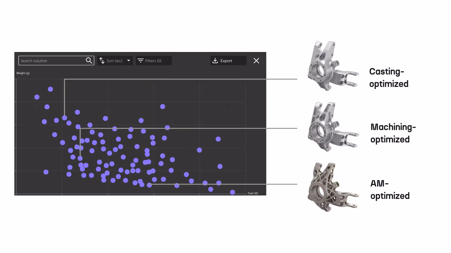
The recent optimization of a high-performance automotive suspension upright demonstrates what becomes possible when manufacturing agnosticism moves from theory to practice. Rather than designing for a single production method and hoping the result would transfer to alternatives, the engineers leveraged Cognitive Design and utilized a Design of Experiments (DoE) workflow to generate over 100 design variations in parallel, each constrained by the rules of its target manufacturing process.

Three Manufacturing Pathways, One Unified Workflow

The workflow evaluated three distinct manufacturing pathways simultaneously, with each pathway enforcing its own set of producibility constraints from the first iteration.

  • Machinable designs were generated with topology optimization strictly constrained to 3-axis and 5-axis accessible features, ensuring that every resulting geometry could be produced with standard CNC toolpaths without requiring specialized fixturing or prohibitive cycle times.
  • Die castable designs enforced strict split lines and draft angles from the outset, preventing the "unbuildable" organic geometry that is typical of standard generative design tools. Wall thicknesses, feature spacing, and undercut avoidance were embedded into the optimization logic rather than checked after the fact.
  • AM-optimized designs explored unconstrained organic forms refined with overhang constraints to ensure self-supporting geometry. This approach reduced both material waste and the post-processing operations that frequently erode the economic case for additive manufacturing.

The critical insight is that these were not three separate projects. They were three branches of a single parametric workflow, sharing the same load cases (2G braking, 3G vertical bumps), the same packaging constraints, and the same performance targets. The only variable was the manufacturing process and its associated rules.

Parallel design exploration interface showing machinable, castable, and AM-optimized upright variants generated from a single parametric workflow
Design exploration interface showing manufacturable upright variants generated from a single parametric workflow

The Trade-Off Matrix: From Guesswork to Data

With all variants generated and automatically evaluated, the engineering team gained access to a transparent matrix of trade-offs that would have been impossible to construct through sequential, single-process iteration.

The titanium AM upright achieved 2.24 kg, delivering 96% of baseline stiffness with organic, stress-optimized geometry. Its estimated production cost, however, reached approximately $850 per unit. The die cast alternative, heavier but dramatically less expensive at roughly $150 per unit, presented a compelling case for volume production where absolute performance is not the sole criterion.

Metric Titanium AM Upright Die Cast Alternative Baseline Steel Component
Mass 2.24 kg Higher (process-dependent) 3.20 kg
Stiffness retention 96% of baseline Process-dependent 100% (baseline)
Estimated unit cost ~$850 ~$150 Legacy cost
Engineering lead time 4 hours (within workflow) 4 hours (within workflow) 96 hours (traditional)
Manufacturability Self-supporting AM geometry Draft angles, split lines enforced Standard fabrication

This holistic assessment extends well beyond price and weight. It integrates manufacturability scoring and structural performance validation under critical load cases. Engineers no longer guess at the best outcome. They compare quantified alternatives and select the solution that best aligns with program objectives, whether those priorities emphasize maximum performance, minimum cost, or the fastest path to production.

Perhaps most significant is the collapse of engineering lead time. What traditionally consumed 96 hours of sequential CAD modeling, simulation setup, and manufacturing review was completed in 4 hours within the unified workflow. That is not an incremental improvement. It is a fundamental change in how concept engineering operates.

Why Early Manufacturing Visibility Changes Everything

The automotive upright case illustrates a principle that extends far beyond a single component. Industry consensus, supported by decades of manufacturing research, holds that roughly 70% of a component's manufacturing cost is determined by decisions made during the design phase. Yet in the traditional workflow, manufacturing visibility arrives far too late to influence those decisions without costly rework.

When a topology-optimized bracket achieves theoretical weight savings of 40% but requires five-axis machining operations, specialized fixtures, and triple the cycle time, the business case collapses. When a die cast housing design reaches tooling only to discover that wall thickness variations will cause porosity defects, the redesign cycle consumes four to six weeks and cascades through supplier commitments, certification timelines, and downstream assembly schedules.

Manufacturing-Driven Design eliminates this pattern by embedding producibility analysis into every design iteration from the concept stage. Within Cognitive Design, the workflow follows four integrated stages:

  1. Geometry Analysis: Automated feature detection scans the model to identify manufacturing-relevant characteristics for each target process.
  2. Risk Identification: The system flags process-specific manufacturability issues, whether that involves draft angle violations for casting, undercut accessibility for machining, or overhang angles for AM.
  3. Automated Repair: Geometry modifications are applied automatically to resolve violations without manual CAD intervention or data transfer to external tools.
  4. Validation: Updated DFM scoring confirms producibility before the variant moves forward in the exploration pipeline.

This four-stage loop executes within seconds for each variant, meaning that engineers exploring 60 or more design alternatives receive manufacturability feedback on every single one. The result is that production problems which traditionally surface during tooling or first-article inspection are identified and resolved during the first hours of concept development, when fixes are fast and inexpensive.

Across deployments, this approach has demonstrated up to a 90% reduction in design-manufacturing iterations, translating directly into shorter development timelines, lower prototyping costs, and fewer late-stage engineering changes.

From Manual Iteration to Intelligent Decision-Making

Generating manufacturable design variants is necessary but not sufficient. The second challenge, equally critical, is navigating the resulting design space with confidence and speed.

Traditional concept exploration follows a painful pattern: engineers iterate manually in CAD based on experience, await feedback from simulation teams, incorporate manufacturing constraints reactively, and track results in spreadsheets that grow unwieldy after the fifth or sixth iteration. Under typical program timelines, teams evaluate fewer than five concepts before committing. That is far too few to identify optimal trade-offs across performance, weight, cost, and producibility.

With Cognitive Design, engineers were able to transform this equation through the Design Explorer, an integrated decision-support environment that automatically extracts and compares key performance indicators across every generated variant. The platform evaluates all alternatives across five dimensions simultaneously:

Structural performance including stress distributions, displacement values, and safety factors under defined load cases. Weight with full mass properties and distribution analysis. Manufacturability with process-specific DFM scoring for die casting, CNC machining, injection molding, and additive manufacturing. Cost with estimated production cost by manufacturing process, covering material, machine time, and pre/post-processing. Sustainability with carbon footprint analysis based on material type, quantity, and process parameters.

Rather than reviewing variants in a visual gallery without analytical context, engineers filter, rank, and compare alternatives using quantified metrics. Every variant maintains a traceable link to its input parameters, constraints, and design logic, ensuring that the rationale behind each decision is documented and auditable.

The parametric workflow architecture that underlies this exploration capability provides an additional, often underestimated advantage: when upstream requirements change (a revised load case, updated packaging constraints, or new material selection), the entire workflow recomputes automatically. There is no manual reconstruction, no broken digital continuity, and no weeks of rework to propagate a single change through dozens of variants. Engineers have reported design changes accommodated in minutes rather than days, with workflows generating 60 or more optimized variants from a single parametric definition.

On-Premises Deployment for Security-Sensitive Industries

Manufacturing agnosticism and multi-process design exploration are computationally intensive, which is why most commercial platforms rely on cloud-based processing. However, for many of the industries that stand to benefit most from this approach, cloud deployment is simply not viable.

Aerospace and defense contractors handle export-controlled data and classified programs that cannot leave secured networks. Automotive OEMs protect competitive design information with strict data governance policies. Even organizations without formal security requirements increasingly recognize data sovereignty as a strategic concern.

Cognitive Design runs entirely on local infrastructure. No cloud connectivity is required, and no data leaves organizational control. All uploaded geometry, generated designs, simulation results, and workflow definitions remain on local servers or workstations. When collaboration is needed, project files in .cds format package complete workflows for secure sharing between team members or sites without relying on external servers.

This architecture ensures that the full capability of manufacturing-driven design, including parallel multi-process exploration, integrated simulation, and automated DFM analysis, is available to organizations operating under the strictest data governance requirements.

Spread the Word
Rhushik Matroja
Rhushik Matroja
CEO

FAQs

Explore our frequently asked questions to understand how our software can benefit you.

No items found.
Nicolas Bellomo

Thanks to Cognitive Design, we were able to rapidly design and validate a structurally optimized tank that fits within our CubeSat constraints, integrates all required functions, and meets demanding pressure requirements. It’s a game-changer for enabling component design exploration high-performance propulsion in small satellite platforms.

Nicolas Bellomo
CTO

Unlock Your Design Potential

Request a demo to see how Cognitive Design by CDS can revolutionize your engineering workflow