
Rhushik Matroja
CEO
.avif)
An aerospace supplier needed to choose between additive manufacturing and CNC machining for a structural door bracket, and requested a quote for both processes on the same geometry. The CNC quote came back far cheaper per part, and on paper the decision looked settled before any engineering work had actually started. Once each process was optimized under its own manufacturing constraints instead of sharing a single drawing, the AM concept came out roughly 25% lighter, at roughly 5 times the unit cost of the CNC baseline. Neither number closes the argument by itself, and treating either one as the final word is exactly the mistake this article addresses. The real question at concept stage is not which process is cheaper on a single geometry, but which trade-off between weight, cost, and production volume actually fits the program.
Most AM versus CNC comparisons in aerospace engineering run on a single geometry, typically the one an engineer already knows how to draw for machining. The comparison looks fair because both quotes describe the same part, submitted to the same suppliers. That apparent fairness is what makes the bias difficult to catch.
Requesting an AM quote and a CNC quote for the same geometry resembles asking a mason to price a house that was designed for wood framing. Each manufacturing process has its own optimal geometry, shaped by different physical constraints: organic load paths and thin walls for AM, accessible pockets and generous radii for 5-axis milling. A geometry drawn with machining habits in mind will always look expensive in AM, not because AM is inherently costlier, but because the part was never designed for it. The comparison, in other words, measures how badly AM handles a machining part rather than how well AM could perform on a part built for its own strengths.
Unit cost is only one line in a much longer decision, and treating it as the whole decision is where most concept-stage evaluations go wrong. Mass matters more in aerospace than in almost any other industry, since every additional kilogram carries a fuel cost over the aircraft's operational life, compounding across every flight cycle the part will see. Several other criteria rarely make it into a first-pass quote comparison, even though they often decide which process actually wins the business case once the full program economics are considered:
• Lead time for prototypes and production runs
• Certification requirements specific to each process
• Geometric flexibility to modify the design late in the program
At the industry level, this quote-first habit has a compounding effect that goes beyond any single part. Every bracket, mount, or fitting evaluated this way inherits the same bias, and across a full aircraft structure, that adds up to dozens of components locked into the process an engineer happened to draw for first, rather than the process best suited to each part's actual loads and mass sensitivity. Programs that only revisit these decisions after a redesign trigger, rather than at concept stage, pay for the bias twice: once in the mass carried through certification, and once in the engineering hours spent reopening a decision that better data would have settled the first time.
Choosing machining by default on a part that would have benefited from AM does not just mean paying a slightly different price per unit. It means carrying extra mass through certification and every flight cycle for the program's life, a cost no single quote line ever shows.
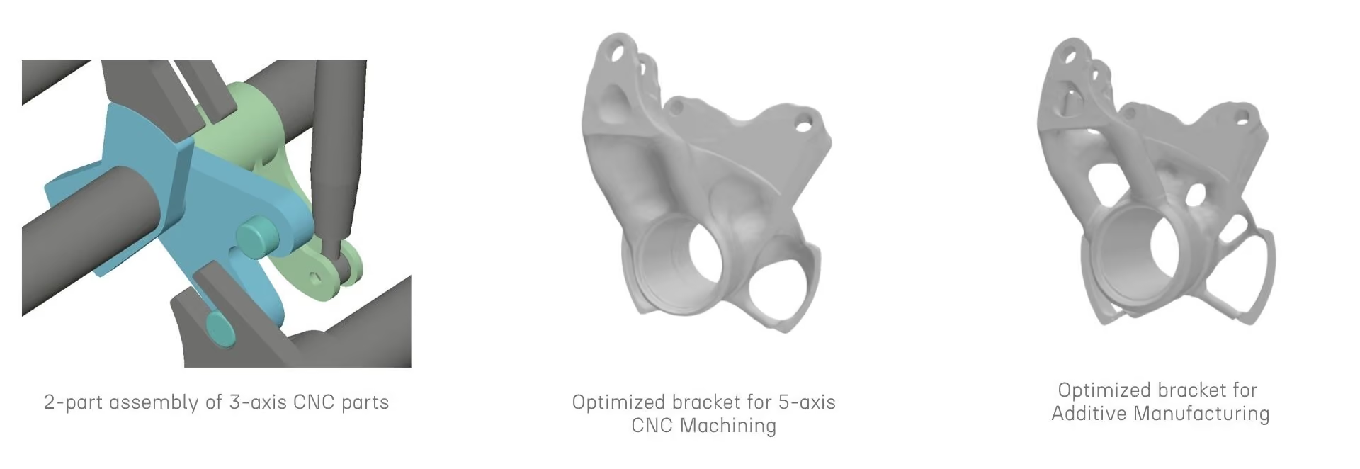
The Potez Aéronautique door bracket case study illustrates this precisely. The 3-axis machined version weighed 0.214 kg and cost 172 euros per part, the 5-axis machined version weighed 0.203 kg and cost 251 euros, and the additively manufactured version weighed 0.165 kg at a manufacturing cost of 913 euros. Looking only at the unit cost column, AM appears to lose decisively against 3-axis machining, by more than 5 times the price. Factoring in the roughly 23% weight reduction changes what "losing" means, because that mass difference compounds across every unit built and every flight flown, in a way the 172-versus-913 comparison never captures on its own. This is precisely the kind of trade-off that a single-metric quote comparison is structurally unable to surface.
Conventional topology optimization tools were not built to run two constraint sets side by side. An engineer evaluating both AM and CNC has to launch two separate workflows, often in two different software environments, then manually reconcile the outputs before any comparison can even begin. This forces a sequential process onto what should be a parallel decision, and every extra step introduces a chance for the two concepts to diverge in ways that make the final comparison less trustworthy than it looks. By the time both workflows converge, the engineer has usually spent enough time on the first concept that revisiting its assumptions to match the second becomes impractical under program deadlines.
.avif)
Additive manufacturing and CNC machining fail in different ways when a geometry ignores their constraints. Each process carries its own set of constraints that need to shape the geometry from the start:
• AM: overhang angles and minimum wall thickness, to avoid support structures and print failures
• CNC: tool accessibility, radii, and fixturing surfaces, built into the design before generation begins
When these constraints are applied as an afterthought rather than shaping the generation process itself, the resulting concepts are not representative of what either process can actually produce, and the engineering team ends up validating a design that will need rework the moment it reaches manufacturing. Certification adds another layer to this, since AM and CNC parts are qualified against different process controls, and a concept that ignores process-specific constraints during generation is unlikely to pass the qualification review built around either process without a redesign cycle.
.png)
Even once two concepts exist, mass, cost, and manufacturability are rarely calculated the same way across both. One workflow might report a safety factor under static loads only, while the other includes fatigue considerations, and the decision-maker ends up reconciling numbers pulled from different sources under different assumptions. That reconciliation work, done manually, is where most concept-stage comparisons quietly lose their rigor, and it is rarely visible in the final design review deck that presents the decision as settled. A reviewer reading the final numbers has no way to tell whether the mass figure for one process accounted for the same margins and load cases as the other, unless the underlying assumptions were tracked with the same discipline throughout.
These three root causes share a common thread: none of them are solved by working harder inside the existing tools, since the limitation sits in how the tools are structured rather than in the engineer's diligence. This distinction matters because it points toward a different kind of workflow rather than a better spreadsheet.
Running two exploration branches under process-specific constraints, one shaped by AM limitations and one by CNC limitations, inside the same environment gives both concepts a genuinely fair evaluation. This is where the comparison stops being a debate about which quote to trust and becomes a structured engineering trade-off, grounded in a shared design space rather than two disconnected drawings.
Cognitive Design lets an engineer launch two exploration branches from the same design space and load cases, one constrained by AM parameters like overhang angle and minimum wall thickness, the other by CNC parameters like tool accessibility and fixturing. Each branch produces a concept that is actually manufacturable by its own process, rather than a single geometry forced to serve both, and the underlying Manufacturing-Driven Design engine handles both constraint sets without requiring separate CAD environments for each. The AM branch explores organic, weight-driven topologies within its overhang and thickness limits, while the CNC branch explores geometries that respect tool reach and fixturing, and both start from the same loads rather than from two independently interpreted requirement sets.
Once both branches converge, every variant, AM and CNC alike, appears in the same Design Explorer with the same calculated metrics:
• Mass
• Von Mises stress
• Safety factor
• Unit cost
This distinction matters because a shared metric set removes the reconciliation step that undermines most manual comparisons, and gives the engineering team one dataset to defend at design review rather than two. As a result, the conversation between design and manufacturing teams shifts from arguing over whose numbers are right to discussing which trade-off the program should accept, a form of Concurrent Engineering that traditional sequential workflows rarely support. A manufacturing engineer reviewing the AM branch and a machining specialist reviewing the CNC branch are, for the first time, looking at figures generated under the same assumptions, which shortens the design review discussion considerably.
.avif)
On the Potez Aéronautique structural door bracket, running 3-axis machining, 5-axis machining, and AM concepts through process-specific optimization cut exploration time by roughly 85% and gave the engineering team a documented, quantified basis for the decision rather than a single supplier quote.
A further simulation-driven design pass on the AM concept reduced weight by an additional ~10% and improved Von Mises stress performance by ~5%, refining the geometry beyond what topology optimization alone produced. This approach adds cost per unit, a trade-off the Potez engineering team had to weigh explicitly against the structural gains achieved, rather than a result that automatically settles in favor of one process. In practice, the right answer depends on how much the program values the weight reduction against production volume and the unit cost gap, not on which process wins a single metric in isolation. By contrast, a quote-based comparison run at the start of the same project would have closed the discussion after the first line item, well before mass, safety factor, and manufacturability had a chance to enter the conversation.
The 85% reduction in exploration time matters here for a second reason beyond speed: it made it practical to run all three process options in the first place, rather than settling for whichever single comparison the schedule allowed.
Getting started with process-optimized comparison means working through a few concrete steps:
.avif)
See the methodology in practice, or download the full case study to review the complete comparison workflow.
Explore our frequently asked questions to understand how our software can benefit you.
The comparison silently favors whichever process the geometry was originally designed for, usually CNC machining, because the part was never shaped around AM's own constraints in the first place.
AM performs best on organic, weight-optimized shapes with thin walls and internal lattice structures, features a machining-oriented geometry rarely includes, so the AM quote ends up pricing an unfavorable design rather than reflecting AM's real potential on that part.
Mass, lead time, certification requirements, and geometric flexibility for future design changes all affect the total program outcome, not just the price of the first batch of parts produced.
On the Potez Aéronautique bracket, running process-optimized concepts in parallel cut exploration time by roughly 85% compared to running separate traditional workflows for each process in sequence.
Not always, but in this case AM carried a meaningfully higher unit cost in exchange for a lighter part, and the right choice depends on how the program weighs that trade-off against production volume and lifecycle mass impact.
DFM is the practice of shaping a design around the physical limits of how it will be produced, such as overhang angles for AM or tool accessibility for machining, and a single generic DFM pass cannot represent both processes at once without favoring one of them by default.

Request a demo to see how Cognitive Design by CDS can revolutionize your engineering workflow
.avif)

.avif)

.avif)