
Alejandro Carcel Lopez
Director of Application Engineering & Services
.avif)
A pressurized propulsion tank sits at the intersection of two demands that pull in opposite directions. It must survive cyclic internal pressure, launch loads, and orbital thermal cycling with a wide safety margin, while carrying as little mass as possible into orbit. T4i, an Italian New Space company building propulsion systems for small satellites, worked through this tension on a 1U CubeSat propulsion tank rated for 40 bar internal pressure. Using topology optimization (TO) integrated with simulation-driven design (SDD), the team reduced Von Mises stress concentrations by 85% and displacement by 96%, while compressing the engineering workflow by a factor of 10.
A propulsion tank ranks among the most demanding structural parts on a satellite, because it combines pressure containment, launch survivability, and orbital thermal exposure inside a single, mass-constrained envelope. The part must hold cyclic fill and drain pressure without leaking, absorb the quasi-static and vibratory loads of ascent, and keep its mechanical properties stable across large temperature swings once in orbit. Every gram removed from the tank is a gram available for payload, propellant, or additional instrumentation, which is why lightweighting on this specific component carries outsized mission value.
Engineers approaching this problem inherit a paradox described later in this article: a design can pass every structural check and still be far from optimal. This case shows how T4i closed that gap, using a workflow that treats internal pressure as a physical variable inside the optimization loop rather than a fixed boundary condition applied after the geometry is frozen.
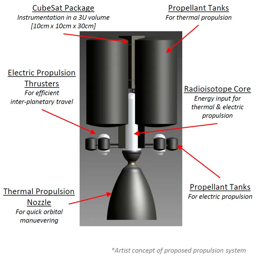
Every optimization decision on this tank traces back to four coupled requirements: pressure containment, launch survivability, thermal stability, and interface preservation. Getting any one of these wrong turns an optimized concept into a part that fails qualification, so each constraint has to be encoded explicitly before the first iteration runs.
The tank operates under cyclic internal pressure through repeated fill and drain cycles, and the design space must additionally accommodate proof pressure and burst pressure checks with safety factors set per ECSS-E-ST-32 (European Cooperation for Space Standardization). Launch loads add quasi-static accelerations and random vibration on top of the pressure cycling, values that vary by launch vehicle and are typically specified late in a program. For this article, launch load values are presented as industry-typical ECSS ranges rather than confirmed T4i-specific figures, since the case record does not disclose the exact vehicle interface data.
Once in orbit, the tank cycles between eclipse and direct sunlight, a swing that can move mechanical properties measurably depending on the alloy and cycle count over the mission life. Differential thermal expansion between the tank and its mounting structure adds a secondary load path that a purely mechanical analysis would miss, since the mounting flange and the tank body do not expand at the same rate under a temperature swing.
On the T4i tank, the material selected was Scalmalloy, an aluminum-scandium alloy produced through laser powder bed fusion (L-PBF) additive manufacturing, chosen for its favorable strength-to-density ratio in an AM-compatible process. This choice matters for the workflow downstream, because every manufacturability check in Step 5 is calibrated against L-PBF process limits rather than the machining constraints that a titanium or conventional aluminum tank would carry.
A 1U CubeSat envelope leaves little room for the generous margins that a larger satellite bus can absorb without consequence, since the tank shares its already tight volume with propellant, avionics, and structure. A design that would be an acceptable compromise on a larger platform becomes a binding constraint at CubeSat scale, which is part of why T4i treated this project as worth the tooling investment described in the next section, rather than shipping the heritage design as-is.
The design space excludes mounting interfaces, fluid fill and drain fittings, and sensor ports, all of which carry geometric tolerances that optimization must never touch. On this project, the true design space was narrowed to the tank's internal wall and its adjoining support structure, not the full pressurized envelope, which is the detail that shapes every step of the workflow described below.
The conventional route to a qualified tank starts from a heritage design or an analytical dome profile, elliptical, spherical, or torispherical, sized against classical pressure vessel formulas. The engineer runs a finite element analysis (FEA) pass, manually thickens any zone that shows a stress concentration, and reruns the analysis until every check clears the required safety factor. The result is a design that passes qualification but was never asked whether it could pass at lower mass.
.avif)
Classical pressure vessel formulas size the dome and cylinder wall against membrane stress theory, which assumes an idealized, unbroken shell under uniform pressure. Real tanks are not unbroken shells: mounting flanges, fluid fittings, and sensor bosses interrupt the idealized geometry and create local stress concentrations that the analytical formula never predicted. The engineer's manual response, adding local thickness around each concentration, treats the symptom without ever asking whether a different global geometry would remove the concentration altogether.
A tank that clears structural analysis with a safety factor of 2.5 when the program requires 1.5 is not, by that fact alone, a safe design. It is an oversized one, carrying margin nobody asked for and nobody can spend on payload. Without a systematic way to explore the space between the required and the achieved safety factor, an engineer has no basis for knowing how much of that margin is recoverable, and the heritage design ships as-is because reworking it manually is too slow to justify against schedule pressure. The traditional workflow is not wrong, it is simply incomplete: it answers "does this design hold," never "what is the lightest design that still holds."
Cognitive Design, CDS's advanced concept engineering platform, restructures this sequence around a single deterministic loop rather than a manual thicken-and-recheck cycle. The workflow below traces the five steps that took T4i from a heritage-validated tank to an optimized one, each with the specific parameters used on this project.
The workflow begins by importing the tank geometry as a BRep (CAD-exact) file and marking three zone types: the internal wall available for optimization, the support structure and stiffeners available for a separate lattice exploration, and the non-modifiable functional zones, mounting flanges, fluid fittings, and sensor ports. This zone separation is the single most consequential decision in the workflow, because it determines what the optimizer is allowed to touch before a single iteration runs.
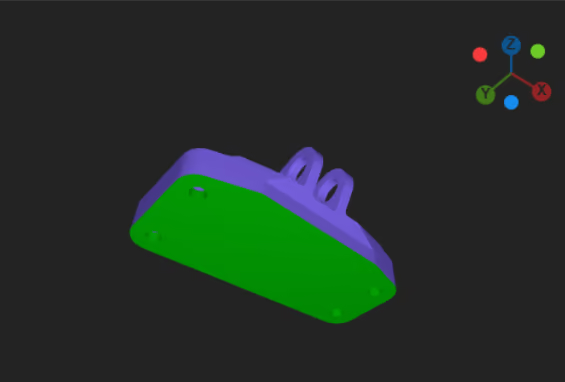
Internal pressure, launch loads, and thermal cycling are configured as independent load cases, each carrying its own safety factor per ECSS. Internal pressure is set as a follower load, meaning the platform recalculates its direction and magnitude against the surface normal at every iteration rather than applying it as a fixed vector frozen at the starting geometry. Launch loads are added as quasi-static accelerations combined with the pressure case, since a tank at maximum operating pressure during ascent sees both effects simultaneously rather than sequentially, and treating them as separate, non-combined checks would understate the worst-case stress state.
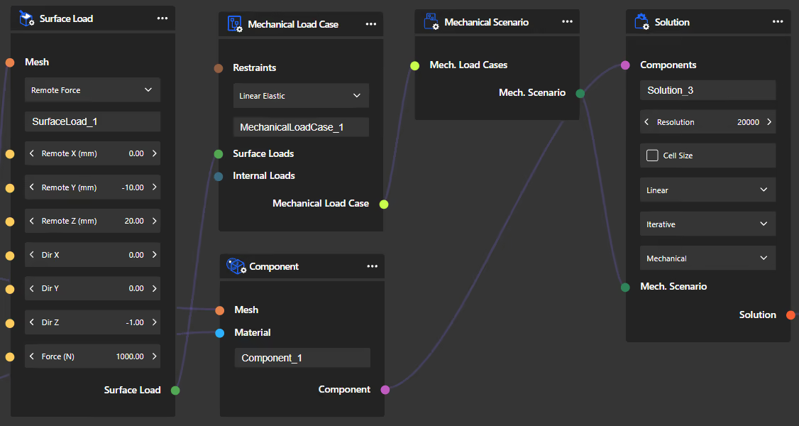
Topology optimization runs directly on the design space defined by the tank's internal wall, using the follower-load pressure configuration from Step 2 so that each iteration reflects the actual pressure distribution on the evolving geometry. A meshless finite element solver validates every iteration in real time, without the manual meshing step a conventional FEA workflow would require, letting the engineer watch the stress field converge rather than wait for a batch result.
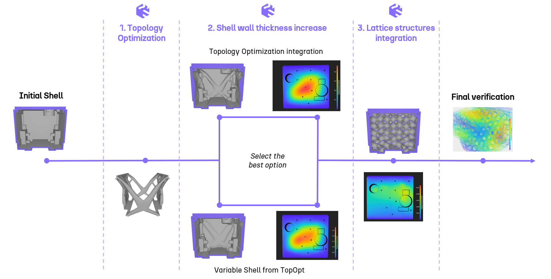
The optimized wall geometry from Step 3 is merged with the existing tank shell through a Boolean operation, producing a single continuous solid rather than two geometries stitched together at a visible seam. A Variable Shell operation is then applied across the merged geometry, producing a continuous, optimized thickness distribution with Simulation-Driven Design at the interface between the newly optimized zone and the original shell, which is what preserves both structural continuity and the pressure boundary's integrity.
Separately, the support structure and stiffeners go through their own design of experiments (DoE), sweeping multiple lattice families, cell size, and strut thickness, evaluated on max Von Mises, mass, displacement, and safety factor for each variant. On the T4i tank, this lattice DoE identified a Fischer-Koch triply periodic minimal surface as the optimal configuration, found in 4.5 hours of exploration, a distinction worth underlining given that a lattice cannot itself serve as a pressure boundary. It reinforces the support structure; it does not replace the sealed wall.
.avif)
Every candidate geometry passes through a manufacturing-driven design (MDD) check calibrated for L-PBF, verifying minimum wall thickness, self-supporting angles, and powder removal paths before any concept is considered final. Any flagged zone routes back through a correction node, a minimum thickness offset or a supported-hole adjustment, before the geometry re-enters validation, which keeps the manufacturability check from becoming a late-stage gate that stalls the whole program.
.avif)
The engineer compares finalists in the Design Explorer, selects the concept that minimizes mass subject to the required safety factor, and exports the result as a STEP file with a full traceability report covering every KPI generated during exploration, a record that matters as much for certification review as for the design decision itself.
T4i builds propulsion systems for small satellites and CubeSats, a segment where every gram of structural mass competes directly against propellant load or payload capacity. The engineering challenge on this project was to reduce the mass of a 1U CubeSat propulsion tank rated for 40 bar internal pressure without reopening the qualification basis established for the heritage design. Applying the workflow described above, the team found that stress concentrations in the heritage dome geometry could be reduced by 85% once the internal wall was treated as an open design space rather than a fixed inheritance from the previous program.
T4i described Cognitive Design as enabling the team to rapidly design and validate a structurally optimized tank fitting within CubeSat constraints, integrating all required functions while meeting demanding pressure requirements. He characterized the platform as a meaningful step forward for exploring component design in high-performance propulsion for small satellite platforms.
The comparison below sets the heritage-validated baseline against the optimized concept across the metrics that mattered for qualification and for mission mass budget.
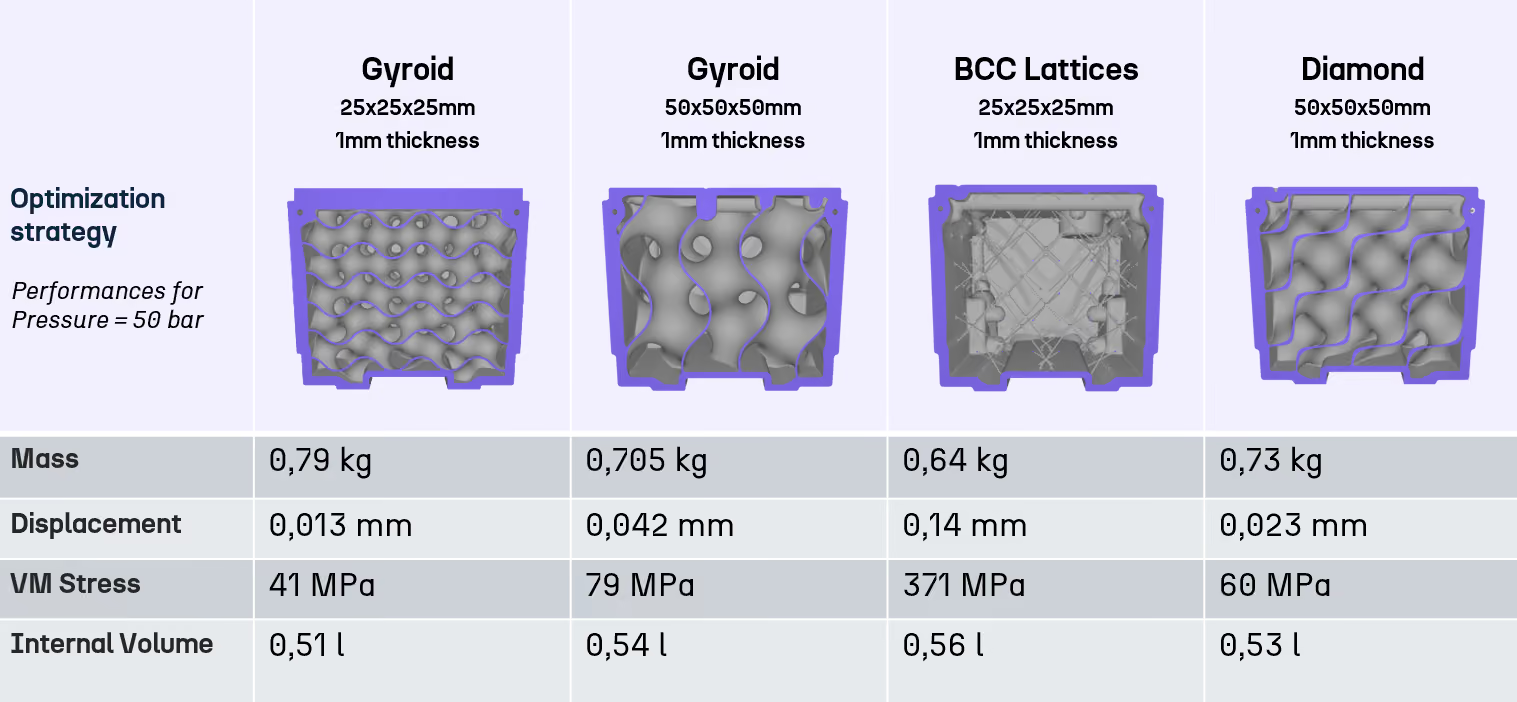
A 96% reduction in displacement matters as much as the stress result, because it is the metric most closely tied to functional clearance at the mounting interface, a margin the heritage design never quantified because it was never asked to explore beyond validation. The mass reduction this unlocks translates directly into freed payload capacity or the option to raise operating pressure on future variants, and it did so without extending the safety factor beyond what the program required, which is the trade-off worth stating plainly: this workflow does not manufacture margin out of nothing, it recovers margin that a validation-only process leaves undiscovered.
Optimization at this depth is worth the investment when a program is building a constellation, launching a genuinely new design, or pushing toward a performance upgrade on an existing platform, since the tooling and workflow setup cost amortizes fastest across repeated or high-value parts. Handling internal pressure as a follower load is non-negotiable for any pressurized structure, because a fixed-load approximation produces a geometry that looks converged in the optimizer but fails once real pressure is reapplied in validation FEA. Finally, separating the pressure-retaining wall from the support structure in the design of experiments is what let T4i explore lattice reinforcement aggressively without ever putting the sealed boundary at risk, a distinction that generalizes to any pressurized component, from pressurant tanks to pressurized heat exchangers.
Programs evaluating whether this approach fits their next part should look first at whether the current design was validated once and never revisited, since that is the strongest signal of recoverable margin. A component that has gone through several manual redesign cycles already has some of this exploration baked in, which lowers the expected gain compared to a heritage design carried forward unchanged across programs. The tooling investment also pays off faster on parts that repeat across a product line or a constellation, where the same workflow, once built, applies to each subsequent variant in hours rather than weeks.
See the full T4i case study or webinar replay for the complete engineering breakdown, or explore how this methodology applies to your next pressurized component with a demo of Cognitive Design.
Explore our frequently asked questions to understand how our software can benefit you.
Internal pressure acts perpendicular to the surface it loads, so its direction changes as the geometry changes during optimization. Treating it as a fixed-direction load produces a concept that looks valid in the optimizer but fails once the true, geometry-dependent pressure is reapplied in validation FEA.
A validated design passes the required structural checks, often with margin well beyond what the program needs. An optimized design starts from the same checks but systematically explores the design space to find the lightest geometry that still clears the required safety factor, rather than stopping at the first design that passes.
Applying topology optimization to the internal wall itself, rather than only to secondary structure, lets the optimizer reshape the dome and wall geometry where the actual stress concentrations occur. On the T4i tank, this is where the largest stress and mass gains were available.
The Boolean merge fuses the optimized wall geometry with the existing shell into one continuous solid, and the subsequent Variable Shell operation distributes thickness smoothly across that merged geometry. This preserves both structural continuity and the sealed pressure boundary at the interface between the two zones.
On the T4i project, the lattice design of experiments across multiple families and parameters converged on the optimal Fischer-Koch configuration in 4.5 hours, compared to a conventional sequential FEA workflow that would typically need days to evaluate a fraction as many variants.
Yes. The same principles, follower-load pressure, strict separation of functional zones, and two-level validation, apply to pressurant tanks, pressurized heat exchangers, and other sealed structures where mass and pressure containment compete directly.
The design must satisfy minimum wall thickness for reliable fusion, self-supporting angles to avoid unsupported overhangs, and clear powder removal paths through the internal cavities, all checked through manufacturing-driven design before any concept is exported for build.

Request a demo to see how Cognitive Design by CDS can revolutionize your engineering workflow
.avif)
.avif)

.avif)
