
Rhushik Matroja
CEO
.avif)
A satellite program enters its second design phase. The structural team has already validated load cases, confirmed material specifications, and cleared a full topology optimization pass on the reference antenna bracket. Then the antenna configuration changes. The reflector diameter shifts by 40 millimeters, and the mounting interface repositions accordingly. What follows is not a revision. It is a restart: a new CAD model, a rebuilt FEA setup, a fresh manufacturability check, and another four weeks of senior engineering time absorbed by a bracket that shares 90% of its functional logic with the previous version.
This scenario is not exceptional. Across satellite programs, launch vehicle structures, and defense platforms, structural bracket families are redesigned variant by variant, even when the underlying engineering problem remains essentially identical. Load environments do not change. Materials do not change. Manufacturing processes do not change. Only the geometry shifts, and that shift is sufficient to reset the entire workflow under conventional CAD methodologies.
At the program level, the cumulative effect is substantial. For example, on a satellite requiring 80+ tripod variants, even a conservative estimate of 10 additional hours of rework per variant produces 800 engineering hours absorbed by repetition rather than by exploration, optimization, or innovation.
When the geometry of a bracket variant changes, conventional engineering workflows do not adapt to that change. Topology optimization setups, load case configurations, and manufacturability checks are each tied to a specific geometry, and a dimensional shift forces a rebuild rather than an update. This constraint is architectural, not procedural. Standard CAD environments were designed to manage individual parts, not to carry structural intelligence across an entire part family.
Three interdependent root causes explain why this produces such significant engineering overhead in practice.
In a conventional workflow, the structural intelligence behind a bracket design resides outside the geometry file. Load case definitions, preservation zones for mounting interfaces, and topology optimization constraints are maintained separately, in FEA files, engineering notes, or the institutional knowledge of the senior engineers who built them.
When a new variant requires a modified envelope, the engineer returns to the geometry and reconstructs that structural context manually, from scratch. The CAD model stores dimensional relationships between features. It does not store why those features were shaped the way they were.
This distinction becomes increasingly costly as a program scales. On a family spanning dozens of variants with essentially the same functional logic, the knowledge accumulated on the first variant provides no formal leverage on the second. The reconstruction cycle repeats multiple times, each iteration consuming senior engineering time that could be directed toward exploring better designs.
The consequences of this architecture extend beyond lost time. When engineers anticipate a full rebuild for each new variant, they respond rationally by narrowing the scope of their exploration. In practice, this means:
The design that reaches manufacturing is therefore not the structural optimum. It is the best result achievable within the time available.
.avif)
The second root cause compounds the first. Topology optimization, which determines the optimal distribution of material within a defined design space subject to specified structural objectives and constraints, requires a configuration that is specific to the geometry being analyzed.
For a given bracket, the engineer defines the design space boundaries, applies boundary conditions for each load case, assigns material properties, specifies non-designable zones at mounting interfaces, and configures manufacturing constraints such as minimum member size or symmetry requirements. That configuration is valid for one geometry. When envelope dimensions change by 40 millimeters, the design space shifts, non-designable zones migrate, and load application points move with the new interface positions. The existing setup requires partial revision at minimum, and complete reconstruction in many cases.
On a 10-variant bracket family, the topology optimization configuration is therefore assembled, to varying degrees, 10 separate times. On an 80-variant program, that overhead accumulates into a structural drag on the program timeline.
The deeper consequence is a measurable reduction in design quality. When engineers face the overhead of rebuilding a setup for each new variant, they reduce the number of candidates they evaluate per variant. A program with sufficient computational capacity to assess 15 to 20 topology solutions per variant will, under schedule pressure, assess three or four. As a result, the design selected is not the structural optimum; it is the best outcome within a deliberately constrained exploration.
The third root cause operates at a different stage of the workflow, but its effect reinforces the same pattern. Manufacturing feasibility review, whether for CNC machining, investment casting, or additive manufacturing, typically occurs after the concept design has been frozen for internal approval.
For a machined aluminum bracket, this means confirming minimum wall thicknesses, adequate fillet radii at concave transitions, and tool accessibility for all critical surfaces at the end of the design cycle, not at the beginning. When a manufacturability issue is identified at this stage, the response is a partial redesign, which in turn triggers a re-run of structural validation.
On a bracket family spanning 80 or more variants, the probability of encountering at least one late-stage manufacturability finding per variant approaches certainty when constraints are not embedded from the start. This is not an incidental risk; it is the predictable output of a workflow that treats manufacturability as a gate rather than as an input.
.avif)
The engineering overhead described above accumulates across three dimensions: time, design quality, and schedule predictability. The three interact in ways that make the total program impact larger than any single line item suggests.
On engineering time, the calculation is direct. Programs requiring 50 or more bracket variants, a figure common in multi-mission satellite programs carrying diverse antenna configurations, can absorb thousands of hours in redundant workflow reconstruction that delivers no new structural value.
On design quality, the effect is less immediately visible but equally consequential. Conservative design decisions made under schedule pressure translate directly into mass. A bracket that carries 15% excess mass relative to its structural optimum contributes to the total dry mass of the satellite. At $3,000 per kilogram to low Earth orbit on a medium-lift vehicle, even modest mass excess per bracket, accumulated across a 140-variant fleet program, carries measurable commercial impact.
On programs where schedule pressure limits design exploration to three or four topology candidates per variant, the mass penalty relative to a fully explored optimum typically falls between 10% and 20% per part. Across a large bracket family, that gap is not negligible.
On schedule predictability, the effect is more operational. Engineering teams that cannot reuse workflow intelligence between variants face serial redesign bottlenecks, where variants that could be processed in parallel are sequenced instead because each one requires senior engineering time to rebuild from scratch.
Parametric workflow automation addresses all three root causes by capturing engineering intent, not just geometry, in a reusable and executable form. A parametric workflow encodes load cases, manufacturing constraints, topology optimization objectives, and design space rules as workflow parameters rather than as properties of a specific geometry file. When the input geometry changes between variants, the workflow adapts. The load cases remain consistent. The manufacturing rules remain enforced.
The engineer's role shifts in a meaningful way. Rather than rebuilding the structural logic from scratch for each variant, the engineer builds it once on the reference variant, validates it against the most geometrically extreme cases in the family, and then runs it across the full set. Variant generation becomes a question of input geometry updates and candidate evaluation, not full workflow reconstruction.
In practice, this represents a categorical change in how programs handle part families. A workflow that conventionally consumed two weeks per variant can be reduced to two working days, with a broader set of design candidates evaluated and manufacturing constraints enforced from the first iteration.
.jpg)
That said, building a parametric workflow requires an upfront investment in configuration and validation that a conventional single-variant design does not. The approach delivers its highest return when the program includes five or more variants sharing a common structural logic, a condition that most bracket families in aerospace and space programs meet by definition.
Thales Alenia Space, one of Europe's leading satellite system integrators, faced exactly this pattern across a family of antenna reflector tripods spanning more than 80 variants. Each tripod shared identical load cases across programs, missions, and antenna architectures, yet differed geometrically in arm dimensions, mounting interface positions, and angular configurations between legs.
Working with CDS, the Thales Alenia Space engineering team built a single parametric workflow (full case study accessible here) capturing the structural logic shared across the entire tripod family. Load cases were encoded once and applied consistently across all variants. Manufacturing constraints for machined aluminum were embedded as hard topology optimization parameters, eliminating late-stage manufacturability findings. The Design Explorer module provided a structured candidate evaluation environment for each variant, mapping mass, structural performance, and feasibility simultaneously across all generated alternatives.
The results quantify the impact directly. The team achieved a 80% reduction in total engineering lead time across the full bracket family, an average mass reduction of 45% per tripod relative to legacy designs, and a per-variant design time of 2 working days, reduced from the previous 2-week cycle.
Based on the work carried out with CDS, the results are highly promising and indicate a meaningful evolution in the way we approach engineering at Thales Alenia Space. — Florent Lebrun, Technology and Innovation Lead, Thales Alenia Space
The 45% mass reduction figure reflects not a more aggressive engineering target, but a more thorough exploration of the design space. When engineers are no longer constrained by the time burden of rebuilding setups per variant, they evaluate more candidates and select the genuinely optimal geometry, rather than the first acceptable one.
Parametric workflow automation is not a universal solution, and the conditions under which it delivers the highest return are worth stating clearly. The approach is most effective when variants share a common structural logic but differ geometrically, when the manufacturing method is consistent across the family, and when program volume justifies the upfront workflow setup investment.
For engineering teams assessing whether the pattern described in this article applies to their program, three diagnostic questions provide a practical starting point:
When two or three of these conditions apply, the engineering overhead being absorbed is not an inherent property of structural bracket design. It is the result of a workflow architecture built for individual parts applied to a part family, and the mismatch is addressable.
Explore our frequently asked questions to understand how our software can benefit you.
After identifying the most promising iteration, Thales Alenia Space and CDS teams were able to design each tripod variant in 2 days, compared to the initial 2 weeks per variant using conventional workflows. This 7x per-variant acceleration, combined with a fully reusable parametric workflow, fundamentally changed the economics of the entire program.
Cognitive Design's node-based parametric workflow architecture allows engineering teams to define a single design chain, then regenerate the full optimization, simulation, and manufacturability pipeline for any new variant by modifying input geometry and boundary conditions. This makes the workflow fully reusable across part families without rebuilding the optimization logic from scratch.
Design automation for structural brackets refers to the use of parametric, reusable workflows that replace manual, variant-by-variant engineering processes. Rather than rebuilding CAD models, running separate FEA setups, and reviewing manufacturability independently for each bracket in a family, a single workflow encapsulates all design intents and automatically recomputes for each new input geometry. Platforms like Cognitive Design implement this through node-based workflows combining topology optimization, simulation-driven design, and manufacturing-driven design, reducing per-variant lead time from weeks to hours.
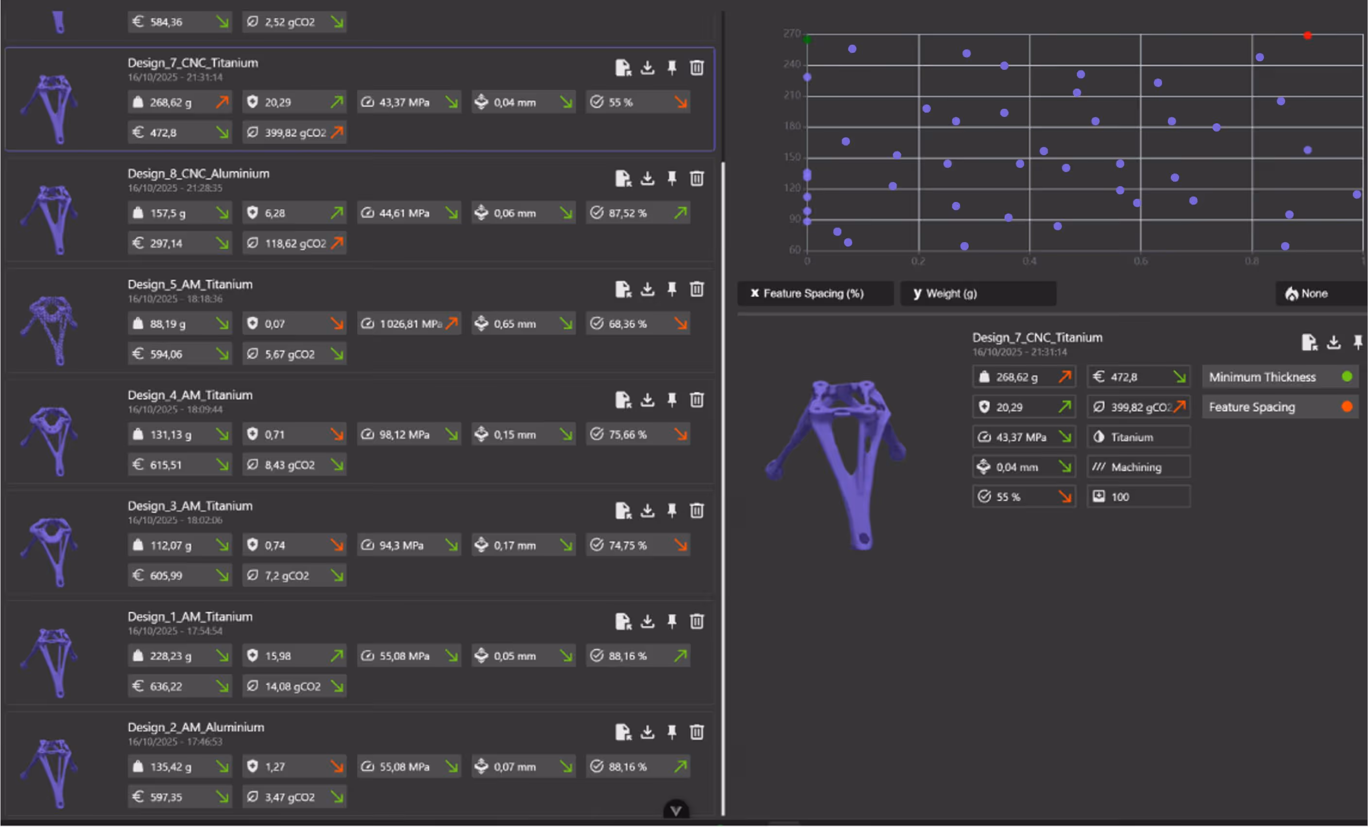
Yes. Cognitive Design's node-based parametric workflow supports simultaneous exploration across additive manufacturing (AM), die casting, and CNC machining within a single session. Manufacturability constraints, cost, and carbon footprint are evaluated concurrently for every iteration, eliminating the need for separate design tracks per process.

Request a demo to see how Cognitive Design by CDS can revolutionize your engineering workflow
.jpg)
.jpg)

.jpg)
