.avif)
Rhushik Matroja
CEO
Generative design was built to solve a specific structural problem: given a load environment and a material, find the lightest viable geometry. It executes that objective with high reliability. The difficulty emerges when the resulting concept enters a production context where cost, not mass, determines whether a design advances to manufacturing. In industrial equipment and machinery, where part families run in medium-to-high volumes and machining time governs unit economics, the lightest concept is rarely the most affordable to produce. The gap between mass-optimal and cost-optimal outcomes is precisely where most generative design programs stall, not for technical reasons, but for methodological ones.
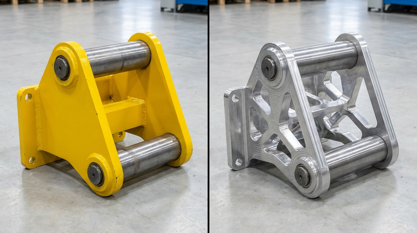
A rotary filler link family developed for a pharmaceutical production line illustrates this tension with uncommon clarity (full case study here). Six links, each optimized for stiffness and fatigue resistance under variable mechanical loads, produced variants ranging from structurally sound to structurally sound and economically unviable, depending entirely on which constraints and objectives governed the exploration. The project team resolved this gap through a structured cost-driven workflow that integrated cost estimation, process-accurate manufacturing constraints, and family-level standardization directly into the design exploration loop. The four practices distilled from that program are described below, with implementation specifics and quantified evidence from the source application.
In industrial production environments, generative design tools applied without cost integration consistently produce geometries that meet structural targets while generating configurations that manufacturing teams cannot quote competitively. The underlying cause is objective function misalignment: the exploration engine minimizes mass while cost variables remain invisible to the optimizer. Three structural mechanisms explain why this gap appears systematically across industrial programs.
These three mechanisms interact: a geometrically unconstrained part, optimized in isolation and costed after concept selection, is the most systematically expensive outcome of a technically sound generative design process. The practices below address each mechanism in sequence.
Cost must appear as a visible driver in the concept exploration tool from the first generated variant, positioned alongside mass and structural stress, not as a calculation run on a shortlist. When unit cost is integrated into the design of experiments at the point of generation, the engineer can filter over-budget variants before committing further development time. This single configuration change reshapes which concepts reach the review stage.
The critical finding from the pharmaceutical link program is that mass-optimal and cost-optimal variants are systematically different concepts, not marginally different versions of the same geometry. On the six-link family, the lightest variants required pocket configurations with depths and transition radii that more than doubled estimated machining cycle time relative to cost-optimal alternatives. Unit cost increased by 15% on the lightest variants despite their material reduction, because machining time governs unit economics for medium-batch precision-machined aluminum parts of this type.
Without cost as a live DoE axis, the engineer's natural workflow ranks variants by mass first, then checks cost on the top performers. This sequence structurally discards cost-competitive alternatives that never enter the ranked view, because they are filtered out before cost is evaluated.
The practice of integrating cost as a first-class output does not prevent the selection of a lightweight concept when that is the correct engineering answer; it ensures that the trade-off between mass and cost is an explicit, informed decision rather than an artefact of which variable was visible at the time of selection.
Cost estimation in Cognitive Design requires three input categories, each corresponding to a distinct cost driver for machined industrial parts:
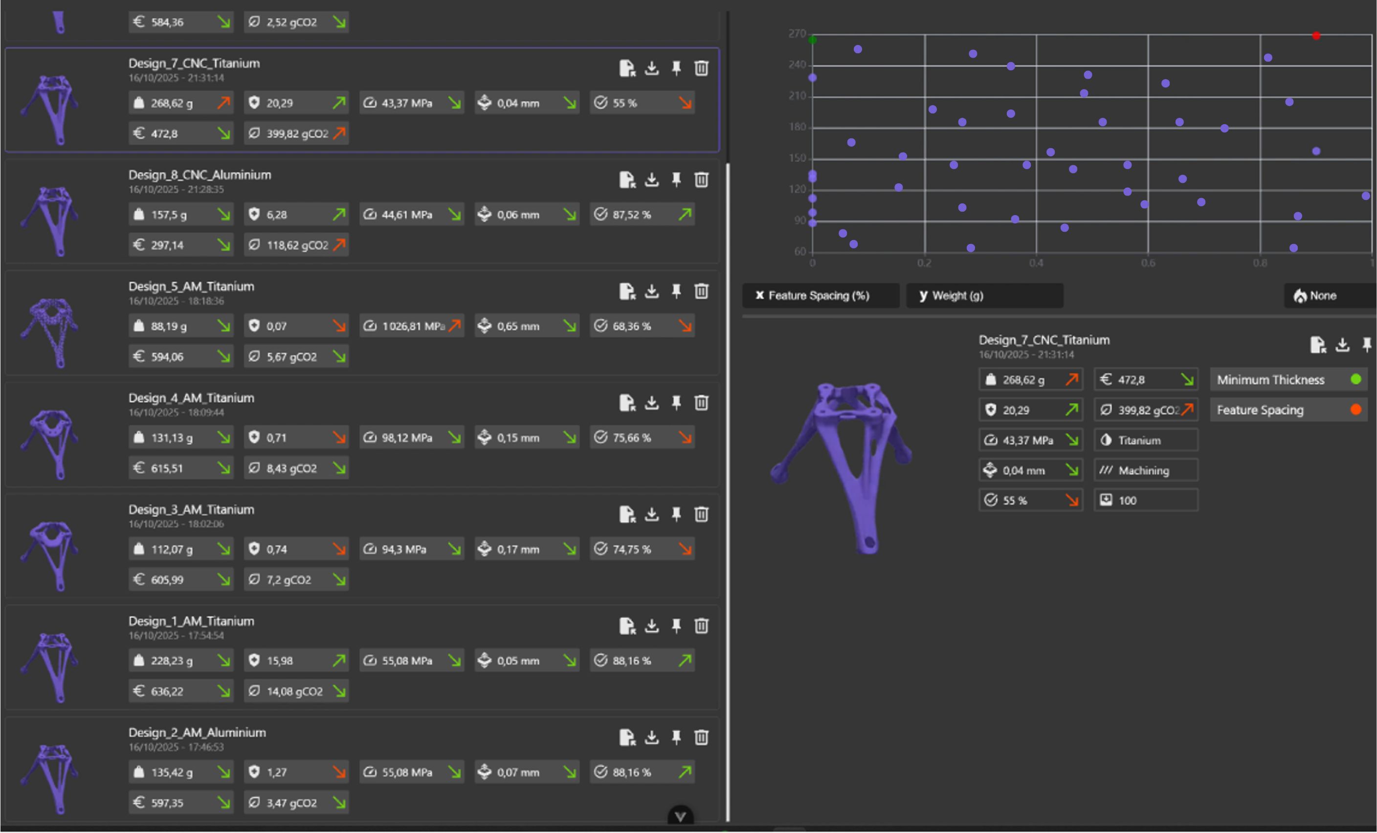
Once configured, cost appears as a selectable axis in the Design Explorer (concept exploration tool), enabling direct trade-off visualization between mass, structural performance, and unit cost across the full generated variant population. Budget thresholds can be applied as filters, eliminating over-cost variants from the selectable design space without removing them from the comparative record.
The most common implementation error is configuring cost models using plant-average machine hourly rates rather than rates specific to the target machine and production cell. When a part could feasibly run on either a standard 3-axis machining center or a 5-axis cell at significantly different hourly rates, using an averaged figure introduces a systematic error that corrupts cost rankings across the variant population. Cost model granularity determines cost ranking reliability; an average input produces an average output whose precision is insufficient for concept selection.
Manufacturing constraints in generative design must reflect the process that will actually produce the part, not the most capable process available in the facility. Optimizing under 5-axis freedom for a part that will be produced on a 3-axis machining center generates concepts that require either a more expensive process than planned or manual rework of the geometry before production release.
.jpg)
Generative design produces geometries within the design envelope that can be defined by the DFM constraints the engineer specifies. When those constraints are broader than the actual production process, the optimizer uses the additional geometric freedom, generating configurations that inherently require the more capable process to manufacture. The resulting cost difference is not marginal.
On the pharmaceutical link family, one variant explored under 5-axis DFM constraints required three setups and long-reach tooling to access deep undercut features distributed across the part geometry. When the same structural target was re-explored under 3+2-axis constraints that reflected the actual production line configuration, the revised concept required two setups with standard tooling, reducing estimated machining cost by 25% at a mass penalty of only 3%. For a part family running in production volumes where machining cost constitutes the majority of unit cost, a 25% reduction is commercially significant by any measure.
This trade-off, 3% additional mass for 25% lower machining cost, represents a clear priority inversion for a production part in this context. It is only accessible if the exploration was configured with accurate process constraints from the outset.
Before configuring DFM constraints in Cognitive Design, confirm three parameters with the methods or manufacturing engineering team:
If multiple processes are genuinely available and process selection remains open at the concept phase, explore them as parallel DoE branches with different constraint sets. The cost output of each branch directly informs the process selection decision, converting what is normally a qualitative discussion into a quantified comparison.
Engineering teams with access to 5-axis capability sometimes configure 5-axis constraints by default, reasoning that broader constraints will produce structurally superior results. This reasoning is correct for performance and incorrect for cost when the production volume does not justify 5-axis cycle time per unit. The constraint configuration should reflect the economically appropriate process for the intended volume, not the technically capable process in the abstract. Process capability and process economics are different criteria, and DFM configuration answers to the latter.
In a part family, total production cost depends not only on each variant's unit cost but on the manufacturing infrastructure shared across the family: fixtures, tool sets, and setup sequences. Optimizing each variant independently maximizes per-part performance but generates the worst possible fixture configuration for the family as a whole. Family-level optimization accepts controlled mass increases per variant to standardize shared manufacturing infrastructure and reduce total program cost.
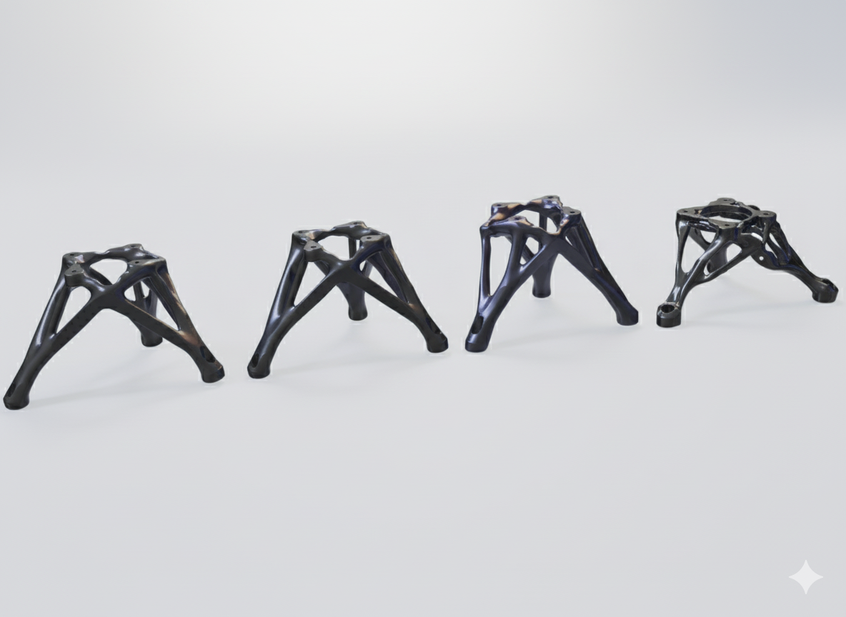
The six links in the pharmaceutical rotary filler program served different angular positions in the filling mechanism, each presenting a slightly different load vector and envelope constraint. Optimized independently, each link converged to a locally sound geometry that placed datum features and clamping surfaces at positions convenient for its individual structural solution, but incompatible with any shared fixture configuration. Six variants with six unique fixture requirements generated a tooling cost for the family that was disproportionate to the aggregate mass savings achieved at the unit level.
When the family was re-explored with a parametric constraint enforcing shared fixture interfaces at two common datum reference frames across all six sizes, the resulting geometries averaged 2% heavier per variant. The fixture count reduced from six unique tools to two shared across the family. Combined savings on fixture fabrication, qualification, and setup time across the production run exceeded the cost of the additional 2% average mass by a significant margin, making family-level optimization the economically dominant strategy for this application.
Family-level optimization in Cognitive Design uses parametric workflow variables to bind specific manufacturing parameters across all variants in the exploration simultaneously. Implementation requires two preparatory steps.
First, identify the manufacturing parameters that can realistically be standardized across sizes: typically fixture datum locations and clamping geometry, tool access directions and minimum clearances, and the maximum part envelope for handling and transfer within the cell.
Second, add a total program cost KPI that aggregates unit cost across all variants together with fixture and tooling amortization at the planned production volume. This composite metric makes the trade-off between per-part mass and family-level tooling savings directly visible and quantifiable before any concept is committed.
.jpg)
Family-level optimization requires that the parametric model encompass all variants simultaneously before the first exploration run begins, which increases initial model setup time relative to single-part exploration. Under schedule pressure, teams sometimes run part-by-part exploration with the stated intention of standardizing fixturing in a subsequent review. In practice, this standardization step does not occur after concept commitment, because each variant's geometry is already approved and the program schedule does not absorb a re-exploration cycle. Family constraints must be defined before the first run, not deferred to a later phase that will not happen.
Cost estimation in Cognitive Design is a parameterized model, not a manufacturing quote. It produces reliable comparative rankings and directionally accurate absolute values, but it does not capture facility-specific variables such as machine availability, current scheduling load, or material batch pricing. Methods department validation on the selected concept, completed before concept freeze, converts an engineering cost model into a production commitment.
On the link family, internal cost estimation accuracy varied predictably with geometric complexity. For prismatic and moderately complex features, estimated and quoted costs agreed within 8%. For geometries with deep pockets and compound-angle surfaces, the gap reached 15%. The commercially important finding was that the cost ranking produced by Cognitive Design was confirmed by the methods estimate in all six cases: the concept identified as cost-optimal during exploration was independently confirmed as cost-optimal in the production quote, even where absolute values diverged.
Validation also surfaced one commercially relevant insight that the volumetric cost model could not encode. For this pharmaceutical application, GMP-grade polishing requirements applied to all wetted surfaces, and polishing time is a direct function of surface continuity, not of machined volume. A modest increase in the fillet radius on one link, adding negligible material, reduced GMP polishing time for that component by 20%, a saving the cost model did not represent and the engineer could not have anticipated without methods input. This modification was applied before concept freeze without any structural performance impact.
Methods validation applies to the selected concept only, not to the full explored design space. The workflow follows four steps: export the STEP file and cost summary report from Cognitive Design for the finalized variant; transmit to the methods department or nominated subcontractor with the target production volume and material specification; compare the returned quote with the Design Explorer estimate; and if the gap exceeds 10%, investigate the discrepancy source and update the cost model parameters for application to future programs in the same manufacturing context.
Requesting detailed quotes on multiple concepts rather than the selected one introduces unnecessary delay and consumes methods department capacity without proportional benefit. Our cost model exists precisely to narrow the field before external validation is required. Sending three concepts for quotation in parallel signals that the internal model did not perform its filtering function, which undermines confidence in the workflow for future programs.
Each of the four practices addresses a distinct cost leakage point in the generative design process, but their effect compounds when applied in sequence rather than selectively.
Cost estimation as a live DoE KPI provides the fundamental filter: only cost-visible concepts reach the shortlist. Process-accurate DFM constraints ensure that cost estimates reflect real production conditions rather than idealized machining scenarios. Family-level optimization prevents fixture and setup complexity from accumulating across the variant population and negating per-part savings. Methods validation converts the engineering output into a quotable commitment before concept freeze eliminates redesign options.
"The lightest concept and the cheapest concept are structurally different geometries, not different points on the same curve. You only see both if cost is in the exploration from the start."
Traditional ApproachCost-Driven Best PracticeMeasured Cost ImpactCost estimated downstream on a shortlisted conceptCost as a live DoE KPI from the first generated variantEliminates 1 to 3 late-stage redesign cycles; lightweighting bias corrected at generationMost permissive available DFM constraints applied by defaultConstraints matched to the actual production process and machine configurationUp to 25% reduction in machining cost at a 3% mass penalty on the link familyEach variant optimized independently, part by partFamily-level parametric constraints standardizing fixtures and setups across variantsFixture count from 6 to 2; total program savings exceeded individual mass penalties across the production runEngineering estimate treated as production costMethods department validation on the selected concept before freezeAbsolute accuracy within 8 to 15% depending on complexity; cost ranking confirmed in all six cases
The sequence is not arbitrary. A team that implements practices 2 and 3 without practice 1 will generate well-constrained, family-optimized variants, but without visibility into whether those variants are within budget from the first exploration cycle. Practice 1 is the prerequisite; practices 2 and 3 govern the quality of the cost signal it produces; practice 4 is the handoff step that converts the engineering decision into a production authorization.
Not every industrial part family justifies the full workflow. The strongest candidates share three defining characteristics: production volume sufficient for unit cost savings to compound meaningfully across the run; a family structure where two or more variants could share manufacturing infrastructure; and a part cost contribution to the finished assembly large enough that a 15 to 25% unit cost reduction is commercially relevant.
The full case study documenting this workflow on the pharmaceutical rotary filler link family is the reference document for teams configuring a cost-driven exploration program for the first time. It includes the complete DoE configuration, variant comparison data, and the methods validation outcome for all six link sizes.

Request a demo to see how Cognitive Design by CDS can revolutionize your engineering workflow
.avif)