
Alejandro Carcel Lopez
Director of Application Engineering & Services
.avif)
Most lightweighting failures do not come from the solver, which always does exactly what it is asked. They come from asking it the wrong thing: a single dominant load case instead of the full operating envelope, or an unprotected functional zone that erodes because nothing told the optimizer to leave it alone. Stiffness loss almost always surfaces at validation, once the part has already been reworked, tooled, or quoted, which is precisely when it becomes expensive to fix. To lightweight a mechanical part without losing stiffness, define the full load case envelope before optimization, protect functional interfaces as fixed boundary conditions, choose a topology method suited to the load environment (density-based or level-set), then validate the combined result with meshless FEA rather than a single load case pass.
Stiffness-preserving lightweighting is the practice of removing mass from a mechanical part through topology optimization while explicitly enforcing the load cases and functional interfaces that determine whether the resulting geometry still meets its structural requirement. Two failure modes account for most of the stiffness lost during otherwise successful mass reduction: optimizing against an incomplete load case, and losing track of which surfaces are functional. Both are procedural mistakes rather than limitations of the algorithm, and both are avoidable once the design space is set up correctly before the solver ever runs.
"The stiffness loss that shows up in validation was never a solver failure. It was a framing decision made several steps earlier."
A solver optimizing against a single dominant load case can produce a geometry that excels on that case but has no margin left once secondary loads are reintroduced. This failure is invisible until validation, because the optimizer reports success against the load case it was given, not against the ones it was never shown.
The fix is procedural rather than algorithmic. Defining the full governing load envelope before the solver runs, rather than after the first result already looks promising, is what separates a part that survives validation from one that requires a second pass.
A raw optimization result carries no inherent record of which surfaces are functional, bolt patterns, bearing seats, sealing faces, and which are free to reshape. Without that distinction enforced upfront, the solver can erode a contact surface simply because it appears structurally under-loaded when viewed in isolation.
The engineer then has to manually re-identify and restore those regions afterward, a step that costs time and often reintroduces the exact mass the optimization had just removed. Retrofitting a single interface this way routinely costs more engineering hours than defining the constraint would have taken at the start, one of the recurring reasons CDS customers cite 56 to 112 hours saved per part once the constraint is defined upfront instead of patched in afterward.
Every stiffness-preserving lightweighting project starts with the same question: which loads govern the geometry, and which loads only rule out local weak points? Treating every load case as equally dominant from the outset produces an overly conservative result that never captures the mass savings the governing case alone would have allowed. Distinguishing the two upfront, rather than discovering the difference at validation, is what determines how much of the theoretical mass saving a program actually keeps.
A governing load case dictates the dominant material distribution, while secondary cases mainly catch local weak points rather than shaping the overall geometry. The practical approach is to run the dominant case first and then reintroduce secondary cases to refine the result, rather than restarting the exploration from scratch every time a new condition is added.
Validating load cases one at a time hides interaction effects: a geometry that passes each case individually can still fail when two loads apply simultaneously through the same feature. On the landing gear actuation bracket, three distinct operating phases (retraction, extension, ground contact) were each defined as their own quasi-static load case within a shared mechanical scenario, applied through the fastener bodies in their real spatial positions.
"On the landing gear bracket, no single load case revealed the true failure mode. Only the combined evaluation did."
Only combined evaluation across all three phases revealed which one actually drove peak stress, information no single-phase validation would have surfaced. Combined validation should be the final gate before a design is considered complete, not an optional check performed only when schedule allows it.
A part is only as good as the interfaces it still fits after optimization, which means preserved regions have to be defined before the solver runs, not identified afterward on the result. Contact meshes are merged into dedicated functional regions that the solver treats as fixed boundary conditions from the first iteration, a setup step that determines whether downstream teams can trust the geometry without re-checking every interface by hand.
Defining these zones upfront lets the solver treat them as fixed boundary conditions, so the geometry never needs a bolt hole or sealing face reconstructed after the fact. This also protects the surfaces a downstream simulation or manufacturing team will reference directly, regardless of how the surrounding organic geometry is reshaped around them.

If a preserved zone is not defined until after the first pass, the team often discovers the solver has already thinned or reshaped a critical interface in ways that are expensive to walk back. Retrofitting a functional surface onto an already-optimized shape usually costs more engineering time than defining the constraint would have taken in the first place, and the mass or stiffness gain reported by the first pass is rarely the gain that survives once the interface is corrected and reblended into the surrounding geometry.
Two topology optimization families exist for stiffness-critical parts: density-based and level-set-based, and neither one is categorically better at meeting a stiffness requirement. Each represents the design space differently, which changes what the resulting geometry looks like and how directly it can be controlled, but both converge on structures that satisfy the stated stiffness target, a distinction worth making explicit since the two are frequently, and incorrectly, presented as a single method with variants.
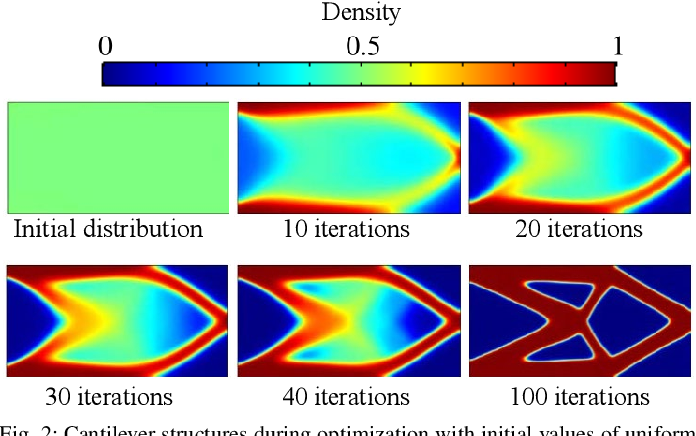
Density-based optimization performs best with one or two clearly dominant load paths, producing strut-and-membrane geometries that concentrate material where the primary load travels. It converges faster and produces more manufacturable, less organic geometry than level-set methods when the load environment is simple, but it is a poor fit when load direction varies significantly across operating conditions, since no single dominant path exists to optimize against.
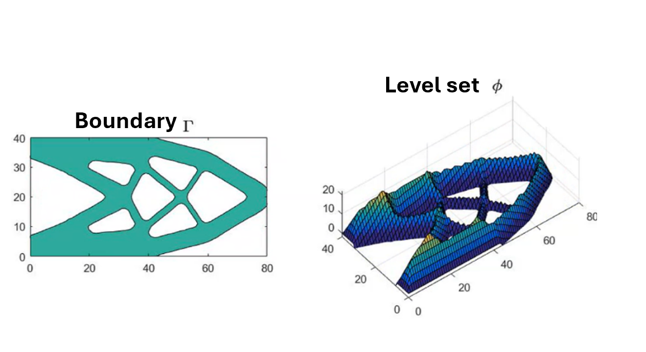
Level set methods represent geometry through explicit, smooth boundaries instead of an implicit density field, which avoids the checkerboarding and jagged surfaces that density-based results often need cleaned up afterward. Engineers get direct control over the shape, size, and position of structural features, including the ability to lock in initial guesses such as mounting points or mating surfaces, something density-based methods cannot offer natively.
Neither method is inherently better for stiffness. Density-based approaches converge faster and suit simple, dominant load paths, while level set suits cases where boundary control and CAD-readiness matter more than fine-grained detail.
A Start Design step seeds the level set optimizer with an initial topology, holes carved through the design space along one or more axes, instead of starting from a fully solid block. This nudges the solver toward different families of results, often more organic and lattice-like, while functional regions such as bolt patterns and load interfaces stay protected through a dedicated boundary thickness parameter.

It is best treated as a design exploration lever rather than a fixed setting. Running a few configurations side by side and comparing them is more productive than tuning a single one in isolation, the same exploration logic behind Design Explorer's approach to comparing candidate geometries later in the workflow.
For a broader comparison of every topology optimization method available today, see the article, What is Topology Optimization? Complete 2026 Guide for Engineers.
A design that passes one FEA run against the governing load case has only proven it survives that one condition, not the full envelope it will face in service. Real validation means re-running the design against the complete load case set before calling it final, a step that on complex assemblies can otherwise account for a large share of total engineering time if done manually and sequentially rather than concurrently.
A single FEA pass against the governing load case confirms survival under that one condition, but says nothing about behavior under the secondary or combined loads the part will see in service. Teams that stop at one pass often discover the margin they reported was specific to that load case, not representative of the full envelope the part actually operates in.
Meshless FEA validates directly against the geometry's native representation without a discrete meshing step, removing the bottleneck that normally slows validation between iterations. Benchmarked against conventional mesh-based FEA, this method holds within 1% on displacement and 5% on stress.
On the supercar brake caliper, structural and thermal meshless FEA ran concurrently on every iteration across three topology styles and two material candidates, rather than validating a single finalist after the fact. This covers the structural and thermal envelope at concept stage: fatigue, crash, and other non-linear dynamic validation still route to a dedicated external solver before certification, a trade-off worth stating plainly since real-time meshless iteration accelerates concept-stage decisions, it does not replace that final step.
Manufacturing constraints can enter a topology optimization workflow in one of two moments: during the algorithm's iterations, or in a targeted post-process step once the geometry is settled, and both are defensible depending on the part. Choosing between them is less about which is superior and more about which trade-off the program can afford, a distinction detailed further in a dedicated comparison article referenced below.
Overhang angle and minimum wall thickness constraints matter most when they are set before the topology is committed rather than checked afterward:
Draft angle, tool access, and parting-line constraints need to be part of the design space definition from the first iteration, not a downstream DFM review that forces rework. On the milling cutter tool head, an organic lattice-oriented topology for DMLS and a pocket-based topology for 5-axis CNC were generated simultaneously from the same load envelope, each with its own process-specific constraints from the start.
Comparing routes this way surfaces which process actually delivers the best stiffness-to-mass result for that part, rather than defaulting to whichever process the legacy geometry happened to favor.

Cognitive Design generates the lightest possible design that still meets the stiffness constraint through level set topology optimization, then refines that result through Simulation-Driven Design and Manufacturing-Driven Design rather than folding every objective into a single pass. On proof-point projects such as Thales Alenia Space's bracket family, this staged approach has delivered up to 45% mass reduction, while Potez Aeronautique reached 30% on an aircraft bracket, both without sacrificing the governing stiffness requirement, keeping the phases distinct is what preserves that gain end to end.
Cognitive Design's generative design capability is built on level set topology optimization, run through the Immersed Method of Moments, producing the lightest possible CAD-ready design that still satisfies the stiffness constraint defined upfront. This first pass stays a pure structural optimization step, manufacturing rules are not folded in yet, so the stiffness result is never diluted by an early manufacturability compromise.
The output then moves into a design refinement phase, handled by Simulation-Driven Design and Manufacturing-Driven Design, rather than being treated as a finished part.
.gif)
Meshless FEA and Simulation-Driven Design (SDD) are best understood as a single loop rather than two separate capabilities:
Manufacturing-Driven Design (MDD) applies as a refinement and post-process step after topology optimization, checking design rules such as minimum thickness and offset live against the already-optimized geometry rather than during the initial generation. On programs where CDS customers report 85% productivity gains across the concept phase, this staged refinement is typically what keeps late-stage rework off the schedule entirely.
.png)
Aggressive stiffness-preserving lightweighting is not always the right call: parts already near their manufacturing floor, low-volume programs, or parts dominated by a non-structural constraint often have little to gain from the full workflow described above and more to lose from the validation overhead it requires. Recognizing these cases early avoids spending the mass-reduction budget where it will not pay back.
Stiffness-preserving lightweighting is a sequencing problem as much as an algorithmic one: define the full load envelope, protect functional interfaces, choose a topology method suited to the load environment, decide when manufacturing constraints enter the loop, and validate the combined result rather than a single pass. For the broader landscape of lightweighting methods beyond topology optimization, see Lightweighting in Engineering Design: Methods, Trade-offs, and Real-World Results, and for what comes after the optimization result itself, From Topology Optimization to Usable CAD. For the underlying reusable methodology, the Reusable Engineering Workflows article covers how the same load case and preserved-region setup can be carried across an entire part family.
The full workflow described here, load case setup, preserved regions, topology choice, validation, and manufacturing constraints, can be orchestrated end to end by AI within Cognitive Design. See it in practice: https://youtu.be/wtbp2fgjw38?si=WrdTSsKajRyucJ2K
Explore our frequently asked questions to understand how our software can benefit you.
Across publicly documented industrial projects, mass reductions range from 30% on heavily loaded automotive parts to 60% on aerospace parts redesigned without legacy geometry constraints, with significant variation depending on the starting geometry and specification constraints.
A Start Design lattice seeds the level set optimizer with an initial topology that the solver then reshapes toward a stiffness-optimal result, while a lattice infill structure is a separate lightweighting approach that fills a defined volume with a repeating unit cell rather than being solved for against a load case.
Rather than validating each load case independently, the optimized geometry is first proven against the single hardest constraint, typically impact, in a solver such as LS-Dyna. The same geometry is then re-validated across the full load case set, including vibration fatigue and thermal cycling, in a second pass. This staged approach confirms that performance gained on the hardest case is not lost once the remaining loads are reintroduced.
Manufacturing-driven design builds process constraints, such as draft or overhang angles, directly into the exploration phase rather than checking them afterward, which reduces the amount of rework needed once a result is obtained.
A preserved region is a functional surface, such as a bolt pattern or bearing seat, explicitly locked as a fixed boundary condition before optimization runs, preventing the solver from eroding an interface that other components or downstream teams depend on.
No. Benchmarking IMM against conventional mesh-based FEA on geometrically complex models shows displacement results within 1% and stress results within 5%, which is within the range of variation typically seen between two independently meshed conventional models.
Aggressive topology optimization often produces concepts where mass reduction and peak stress move in opposite directions: the lightest geometry is rarely the one with the best stress distribution. For a landing gear actuation bracket, an initial optimization pass achieved a 60% mass reduction but raised peak Von Mises stress from 270 MPa to 426 MPa. Rather than discarding the concept or accepting the stress level, Simulation-Driven Design was used to add material back exclusively where stress analysis showed it was needed, specifically variable ribbing targeted at the landing load case, where concentration was highest. This localized addition brought peak stress down to 294 MPa while preserving the 60% mass reduction. Adding material precisely where it earns its weight, rather than uniformly thickening the part, is what makes the final trade-off favorable across both structural performance and mass budget.
Neither is categorically better; generating a topology for each process from the same load envelope and comparing the resulting stiffness-to-mass ratio is the reliable way to decide for a specific part.

Request a demo to see how Cognitive Design by CDS can revolutionize your engineering workflow
.avif)

.avif)
