
Henri De Charnacé
CTO
.avif)
Topology optimization has moved from a research technique to a standard tool in aerospace, automotive, and industrial engineering offices, and the mass savings it delivers on structural parts are well documented in published case work across those industries. Yet a meaningful share of these optimized concepts never leave the file where the optimization solver produced them, because the resulting geometry cannot re-enter the CAD and CAE environment the engineering organization actually works in day to day. Topology optimization is the process of mathematically distributing material within a defined design space, under specified loads and constraints, to produce the lightest geometry that still meets a target performance envelope. The optimization itself succeeds on its own terms, and the part still does not ship, because usability and structural performance turn out to be two separate problems with two separate solutions.
When topology-optimized output cannot be reused directly, the engineering team inherits a second, unplanned project: converting a structurally valid but geometrically raw result into something the downstream CAD, CAE, and manufacturing chain can actually work with. The output of a topology optimization run is a finite element mesh, a voxel density field, or an implicit surface, not native boundary representation (BRep) geometry, and that distinction determines almost everything that follows. The optimization succeeded structurally; whether the result is usable is a separate and largely unresolved question left to the engineer holding the file.
This article addresses that second question directly. It does not evaluate the quality of any particular optimization algorithm, and it does not compare solvers. It focuses on what happens after the optimization run finishes: how optimized geometry moves, or fails to move, back into the CAD and CAE environment where the rest of the program lives. That transition, not the optimization step itself, is where a large share of the engineering effort in a lightweighting program actually goes.
Framed this way, reconstruction is not a finishing touch applied after the real engineering work is done. It is a distinct engineering discipline with its own methods, trade-offs, and failure modes, and treating it as an afterthought is precisely what causes optimized concepts to stall between the solver and the shop floor. The rest of this article works through why that gap exists, how wide it actually is across four distinct reconstruction levels, and where a manufacturing-driven approach to reconstruction changes the calculation.
Optimized geometry resists direct reuse because the mathematics that produce it and the mathematics that CAD kernels expect were never designed to match. Understanding that gap section by section explains why a structurally sound result can still be functionally unusable the moment it reaches a design review.
Finite element solvers produce discretized results: elements, voxels, or density fields distributed across the design space according to where material is structurally justified. CAD kernels built on boundary representation expect continuous, watertight, feature-referenced surfaces, not a cloud of discrete elements with no inherent design history. Importing a raw mesh directly into a CAD environment produces what practitioners call a dumb solid: a shape that looks visually correct on screen but carries no editable features, no parametric relationships, and no record of the design intent that produced it.
[Visual suggestion: side-by-side comparison of a raw FE mesh output and a native CAD BRep solid, showing the structural difference between discretized and continuous geometry. Suggested file name: mesh-vs-brep-topology-optimization-output.jpg. Alt text: Comparison of discretized mesh output versus continuous BRep CAD geometry from topology optimization.]
Topology optimization naturally converges on organic shapes, and it is not unusual for those shapes to include non-manifold regions such as thin ribs or lattice-type connections that have no clean analogue in standard CAD modeling. Because of this, standard CAD operations such as fillet, chamfer, or patterning routinely fail on these surfaces without extensive manual surfacing work beforehand. The same organic complexity that makes topology optimization structurally efficient makes manufacturability checks, such as draft angle and wall thickness verification, considerably harder to run directly on the raw output.
A raw optimization result carries no explicit tags for functional interfaces, preserved zones, or the reasoning that shaped a given region. As a result, the downstream engineer has to manually re-identify which surfaces are functional and which are free-form before any edit or validation step can begin, effectively reverse-engineering intent that existed clearly in the optimization setup but disappeared from its output. This is precisely where a manufacturing-driven approach to reconstruction earns its place: rather than treating every optimized region as an undifferentiated organic surface, reconstruction can reintroduce manufacturing-friendly geometry exactly where it carries engineering intent, prismatic faces where a part will be machined, fillets or draft surfaces where it will be die cast, so the functional meaning of each zone survives the transition instead of having to be rediscovered by hand.
Reconstruction is not a single operation with one outcome; it spans a spectrum of four distinct levels, each trading automation and speed against how much usable engineering structure the result actually recovers. Choosing the right level for a given part is itself an engineering decision, driven by how the geometry will be used downstream rather than by which method is fastest.
Treating these four levels as points on a single spectrum, rather than as competing methods, makes the trade-off explicit: moving from Level 1 to Level 4 buys progressively more editability and design history, and costs progressively more manual engineering time to get there. No level is universally correct, and the sections below work through what each one actually delivers, and what it still leaves for the engineer to do by hand.
.avif)
At the lowest level, the geometry is left as a mesh, optionally smoothed to remove faceting artifacts, with minimal manual effort and fast turnaround. This level suits parts that go directly to additive manufacturing without ever re-entering a CAD environment, since a print-ready mesh is often all the downstream process requires.
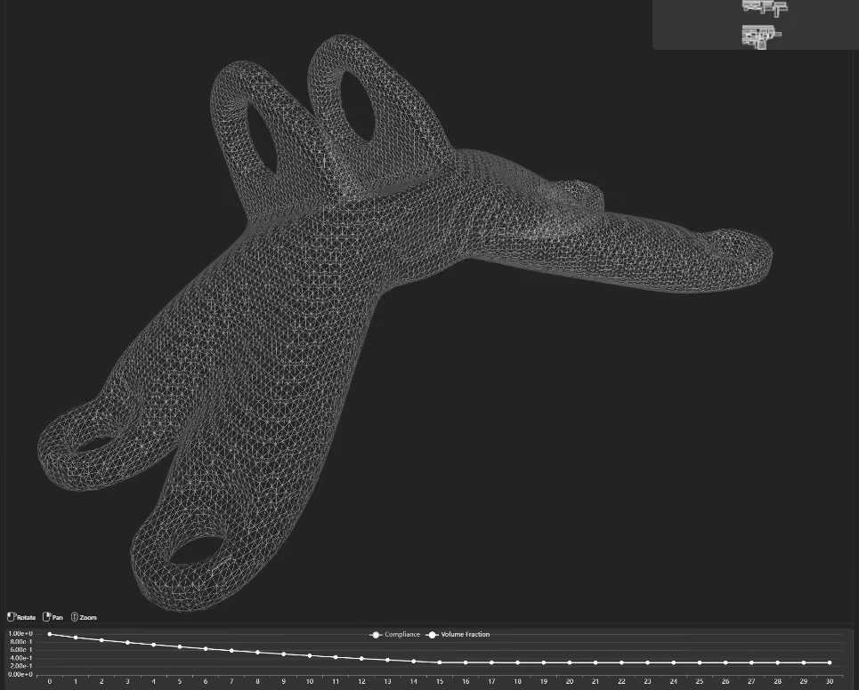
Basic surfacing tools can convert mesh regions into NURBS patches, producing a BRep shell that is cleaner and more exchangeable than a raw mesh, though the result remains largely descriptive rather than editable. This level improves geometric exchange and downstream inspection, but it does not recover engineering features or a parametric design history, which makes it best suited to a part that will be validated once, with limited need for later design changes.
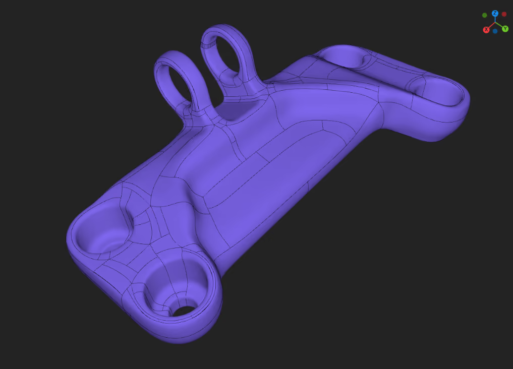
Hybrid BRep reconstruction converts implicit or mesh-based geometry into an exchangeable CAD body while incorporating explicit engineering inputs, such as the original BRep design space and optional functional regions. This is the level at which Cognitive Design positions its BacktoCAD continuity capability, since it restores a usable BRep pathway for downstream CAD and CAE without claiming that every functional surface becomes an analytic CAD primitive or that the result contains a native parametric feature tree. It fits optimized parts that must return to an engineering workflow, provided that geometry resolution and the required level of editability are validated for the application.
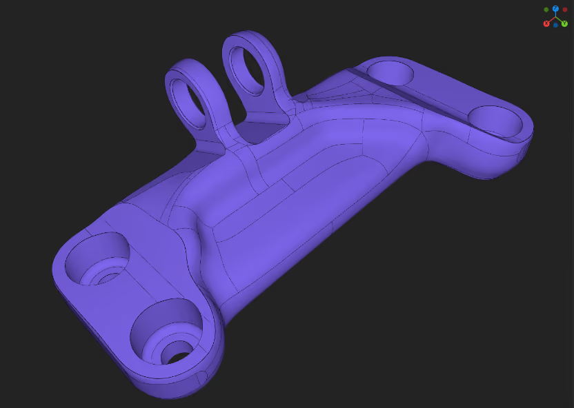
The most complete level rebuilds the part as a tree of parametric operations, extrusions, lofts, patterns, that approximate the optimized shape while remaining fully editable and suitable for generating part-family variants. It carries the highest engineering value and, today, the highest manual effort, and it remains the least automatable step in the entire reconstruction chain. Many engineering teams treat full parametric reconstruction as the end goal, and it should stay clearly distinct in any honest discussion from the hybrid BRep output available today.
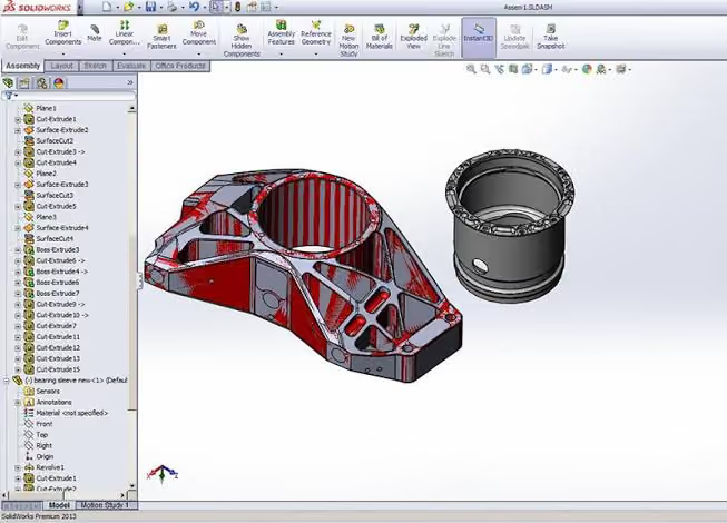
Even where a reconstruction workflow exists, a large share of engineering organizations still fall back on manually rebuilding optimized parts by hand, and understanding why reveals as much about program pressure as about tooling gaps.
The typical manual workflow has the engineer visually inspecting the optimized shape, sketching key cross-sections, then rebuilding surfaces and solids by hand inside native CAD. In doing so, engineers often simplify the shape to make it CAD-friendly, which claws back part of the mass or stiffness gain the optimization achieved in the first place. Absent a reusable parametric link back to the original optimization data, this manual pass repeats in full for every variant of a part family, regardless of how similar the variants are to each other.
This default persists for a straightforward reason: most engineering organizations already own the tools this workflow requires, native CAD seats, experienced surfacing engineers, and established review processes, while a repeatable reconstruction pipeline is a newer capability that has to prove itself before a program will rely on it. Manual rebuilding is not chosen because it is efficient; it is chosen because it is familiar, and familiarity carries real weight when a program schedule leaves no room for a workflow failure discovered mid-project.
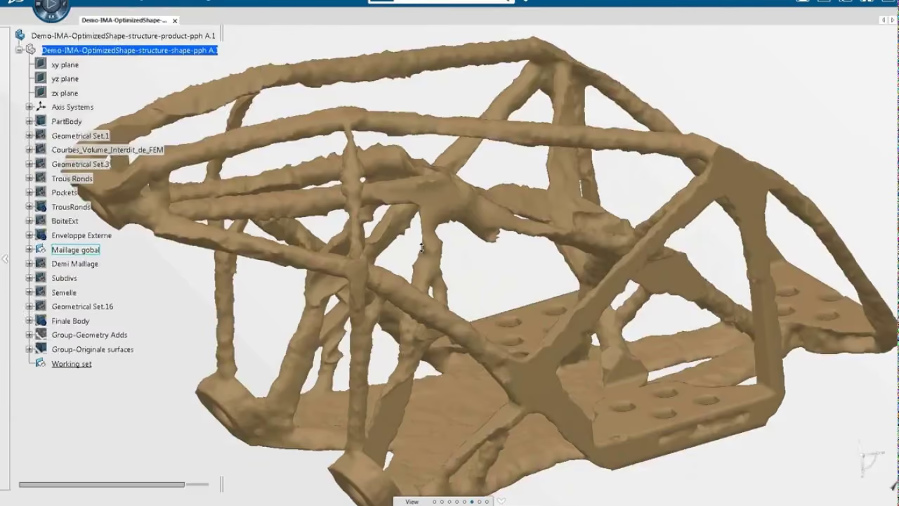
The cost shows up in three distinct places. Manual reconstruction can absorb a substantial share of a program's schedule, though the exact proportion varies too much by part complexity and team experience to state as a single reliable figure. Simplifying the shape for CAD-friendliness reduces the actual mass gain achieved relative to the raw optimized result, trading structural performance for editability. The rationale behind the original shape choice rarely survives the handoff, since a reconstructed CAD file disconnected from the optimization run carries no record of why a given region was shaped the way it was, a gap closely related to what reusable engineering workflows are designed to prevent across a part family.
A reconstructed part with no link back to its optimization run is a part whose design rationale has already been lost, whether or not anyone notices at the next design review.
None of these costs are visible in the optimization report itself, which is part of why they are so easy to underestimate at the planning stage. A program that budgets time for the topology optimization run but not for what happens afterward will discover the reconstruction cost the hard way, usually during the design review where someone asks why the part looks different from what the solver produced.
"Usable" is not a single bar to clear; it means something different to each discipline that touches the part after optimization, and a reconstruction level that satisfies one discipline can leave another discipline stuck. Mapping those requirements against the four reconstruction levels shows why no single level is universally correct.
A design engineer needs parametric editing capability, dimension-driven modifications, and compatibility with whatever CAD system the customer's organization already standardizes on. A raw or smoothed mesh offers none of this, since there is no feature tree to edit, and a NURBS patch shell improves geometric fidelity but stays purely descriptive, so the part can be inspected but not regenerated from a parameter change.
Only hybrid solid reconstruction and full parametric reconstruction restore that editing capability, which is why both score as satisfied on this requirement while the first two levels fall short.
A simulation engineer needs a clean, watertight mesh or surface that remeshes directly for finite element analysis, without artifacts that require manual cleanup before validation can even begin. A raw mesh can sometimes remesh directly, but faceting artifacts and non-manifold regions routinely force manual repair first, and a NURBS patch shell inherits the same limitation since a purely descriptive shell can still carry gaps or overlaps.
Hybrid solid and parametric reconstruction remove that friction by rebuilding the organic regions as continuous, watertight geometry, which is what earns both a satisfied rating here.
A manufacturing engineer needs draft angles, wall thickness, and machinability or moldability to be directly assessable on the reconstructed geometry itself, not inferred from the original optimized shape. For a part destined for laser powder bed fusion, that typically means checking self-supporting overhang angles against a common industry threshold around 45 degrees, checks that are straightforward on clean reconstructed surfaces and considerably harder on a raw mesh, which is why the lowest level rates insufficient.
NURBS patches make those checks possible but still time-consuming across an organic surface, landing at partial, while hybrid solid and parametric reconstruction expose clean, measurable faces in the zones that actually need manufacturing sign-off.
At the program level, what matters is whether the link between the optimization run, its loads, constraints, and material assumptions, and the final CAD file survives the reconstruction process, so the engineering rationale is still available at design review and audit. Raw mesh and NURBS patch reconstruction carry no such link on their own, which is why both rate insufficient.
Hybrid solid reconstruction preserves that connection for the functional zones it rebuilds explicitly, earning a partial rating rather than insufficient, but its organic NURBS regions still fall outside that traceable record. Only a full parametric feature tree captures the complete parameter history end to end, which is why traceability only reaches satisfied for the Feature-Based Parametric Reconstruction.
The table below summarizes this reasoning across all four levels and disciplines.
Cognitive Design treats BacktoCAD as a controlled reconstruction workflow rather than a simple file export. The platform converts FRep or mesh-based geometry into an exchangeable BRep, while using the design space, functional regions, resolution, offsets, and surface density to control what survives the conversion. This approach can restore a practical CAD and CAE pathway for topology-optimized parts, but it does not recreate a native parametric feature tree or eliminate downstream validation.
The workflow begins by carrying explicit engineering inputs into reconstruction instead of asking engineers to infer every critical zone from the final organic shape.
The original Design Space BRep provides the allowable CAD volume used to clip the reconstructed body, while an optional functional-region mesh can preserve or reinforce a local area such as a bolt boss, contact patch, or fixture interface. In the advanced workflow, that functional region is thickened and united with the main geometry before the final BRep conversion and Boolean intersection.
This mechanism preserves functional volume and boundary intent, but it should not be described as automatic semantic recovery of every plane, cylinder, fillet, or manufacturing feature. Design Explorer's KPI tracking, consistent with the broader logic of concept exploration, separately helps the team identify which variant justifies reconstruction by keeping its performance targets visible during selection.
The appropriate conversion route then depends on the representation and condition of the selected geometry.
The established FRep to BRep route converts Cognitive Design's functional representation into boundary representation before the resulting 3D model is exported. It is generally suited to smooth, curved, or prismatic geometries and is more likely to produce an output, although the reconstructed body can contain more surface patches.
The Advanced Mesh to BRep route is intended for rough topology-optimization outputs, shrinkwrapped meshes, and cases requiring explicit functional regions. It converts the input mesh into an implicit signed-distance field, optionally applies a global offset or local reinforcement, reconstructs a quad-dominant BRep, and intersects that body with the original design space.
Both routes can produce CAD-exchange geometry, but the resulting file structure must still be distinguished from parametric reconstruction.
A STEP export can carry the reconstructed BRep into a downstream CAD or CAE system, allowing the body to be inspected, remeshed, referenced, and used in subsequent engineering operations. STEP continuity describes geometric exchange, not recovery of design history: the exported body does not automatically contain the sketches, constraints, dimensions, and ordered features of a native CAD model.
That distinction places the current capability at Level 3 (Hybrid BRep Reconstruction) in the reconstruction spectrum. It offers more downstream utility than a raw mesh or a uniform patch shell, while remaining separate from feature-based parametric reconstruction.
The quality of that BRep is ultimately bounded by the information retained during implicit conversion.

Voxel size is the most influential reconstruction parameter because it determines the smallest geometric information that the implicit field can retain. A useful starting rule is to keep voxel size at or below approximately one third of the smallest feature that must survive; increasing the target quad count afterward can improve surface sampling, but it cannot recover a hole, fillet, or thin connection already erased during voxelization.
Resolution, target quad count, face merging, offset, and Boolean tolerance therefore have to be tuned as an interacting system. Higher resolution can preserve detail but increases memory and compute requirements, while aggressive offsets can thicken weak regions at the cost of dimensional fidelity, and excessive Boolean tolerance can remove small features instead of repairing the underlying geometry.
Manual intervention remains necessary when thin connections fall below the voxel scale, input meshes contain open non-manifold edges, or the design space contains slivers and near-zero-thickness regions that destabilize the final Boolean operation. Lattices and triply periodic minimal surface structures present a separate trade-off: an STL containing the lattice is often more reliable for additive manufacturing, while a parallel STEP model without the lattice can support machining and interface work.
Hybrid BRep reconstruction restores an exchangeable BRep pathway for many downstream workflows, while feature scale, geometry quality, and required CAD editability still determine how much finishing remains.
Reconstruction is not always the right call, and treating it as a default step regardless of context misrepresents its actual value. Four situations make it the wrong investment:
Recognizing these cases matters as much as recognizing when reconstruction pays off. A team that reconstructs every optimized part on principle, regardless of downstream need, spends effort on parts that never required it, while a team that skips reconstruction on a part family that will run for years ends up paying the manual rebuild cost repeatedly instead of once. The right question is never whether reconstruction is possible, since at some level it almost always is, but whether the specific part, program, and part-family outlook justify the investment.
Topology optimization delivers on its structural promise reliably; the industry's open problem sits one step downstream, in getting that optimized geometry back into a form the rest of the engineering organization can actually use. Hybrid BRep reconstruction, of the kind BacktoCAD continuity targets, restores an exchangeable geometry pathway for many design, simulation, and manufacturing workflows, while full parametric reconstruction remains a frontier the industry has not yet automated. Readers building a broader picture of this space may find it useful to start with Topology Optimization: The Complete 2026 Engineering Guide for the optimization step itself, and Implicit Modeling vs. B-Rep: A Technical Comparison for the geometric representation questions this article builds on.
Explore our frequently asked questions to understand how our software can benefit you.
No. Raw topology optimization output is a mesh, voxel field, or implicit surface, none of which carries the continuous, feature-referenced structure that CAD editing operations require. Direct import produces a dumb solid: visually correct, but without editable features or a design history, which is why a dedicated reconstruction step exists between optimization and usable CAD.
A mesh is a discretized surface made of discrete elements with no design history. BRep is continuous boundary representation geometry, watertight and feature-referenced, but a BRep shell produced by basic surfacing can still be purely descriptive rather than editable. Parametric CAD output goes further, storing the part as a tree of editable operations, extrusions, lofts, and patterns, that can be modified and regenerated on demand.
No. STEP is a file format for exchanging geometry between CAD systems, not a guarantee about the internal structure of that geometry. A mesh converted to a STEP-compatible shell is still a descriptive shell once exported; the format changes, but the underlying lack of parametric structure and design history does not.
The proportion varies significantly by part complexity, reconstruction level targeted, and team experience, so no single figure applies universally across programs. What is consistent is where the effort concentrates: re-identifying functional surfaces, rebuilding organic regions by hand, and revalidating the simplified result against the original performance target.
BacktoCAD is Cognitive Design's approach to converting FRep or mesh-based optimized geometry into an exchangeable BRep for downstream CAD and CAE workflows. Depending on the input, the process can use the original design space, optional functional regions, implicit conversion, offsets, and quad-dominant surfacing before STEP export. It does not recreate a native parametric feature tree.
Not as a general capability. Feature-based parametric reconstruction, rebuilding a part as a tree of parametric operations that approximates the optimized shape, remains the least automatable step in the reconstruction spectrum across the industry, and it typically still requires substantial manual engineering work regardless of which platform produced the original optimization.
A clean, watertight reconstruction remeshes directly for finite element analysis, while artifacts left over from a poor reconstruction, non-manifold edges, gaps, or overlapping surfaces, force manual cleanup before validation can proceed. The quality of the reconstruction step directly gates how quickly a simulation engineer can confirm the optimized design still meets its structural targets.
Under the right conditions, yes, though this depends heavily on how much of the shape is simplified during reconstruction. Hybrid solid reconstruction that preserves organic regions as NURBS patches, rather than smoothing them into simpler primitive shapes, tends to retain more of the original mass and stiffness gain than a manual rebuild that trades performance for CAD-friendliness.

Request a demo to see how Cognitive Design by CDS can revolutionize your engineering workflow
.avif)

.avif)
