Henri De Charnacé
CTO
Last updated: November 2026
Design of experiments (DoE) is one of the most mature methods in engineering, yet in mechanical design it is usually applied once the concept is frozen and only dimensions remain to be tuned. DoE in the concept phase reverses that order: it systematically samples the inputs that generate a part's geometry, so that every run of the plan produces a complete concept evaluated on the same criteria.
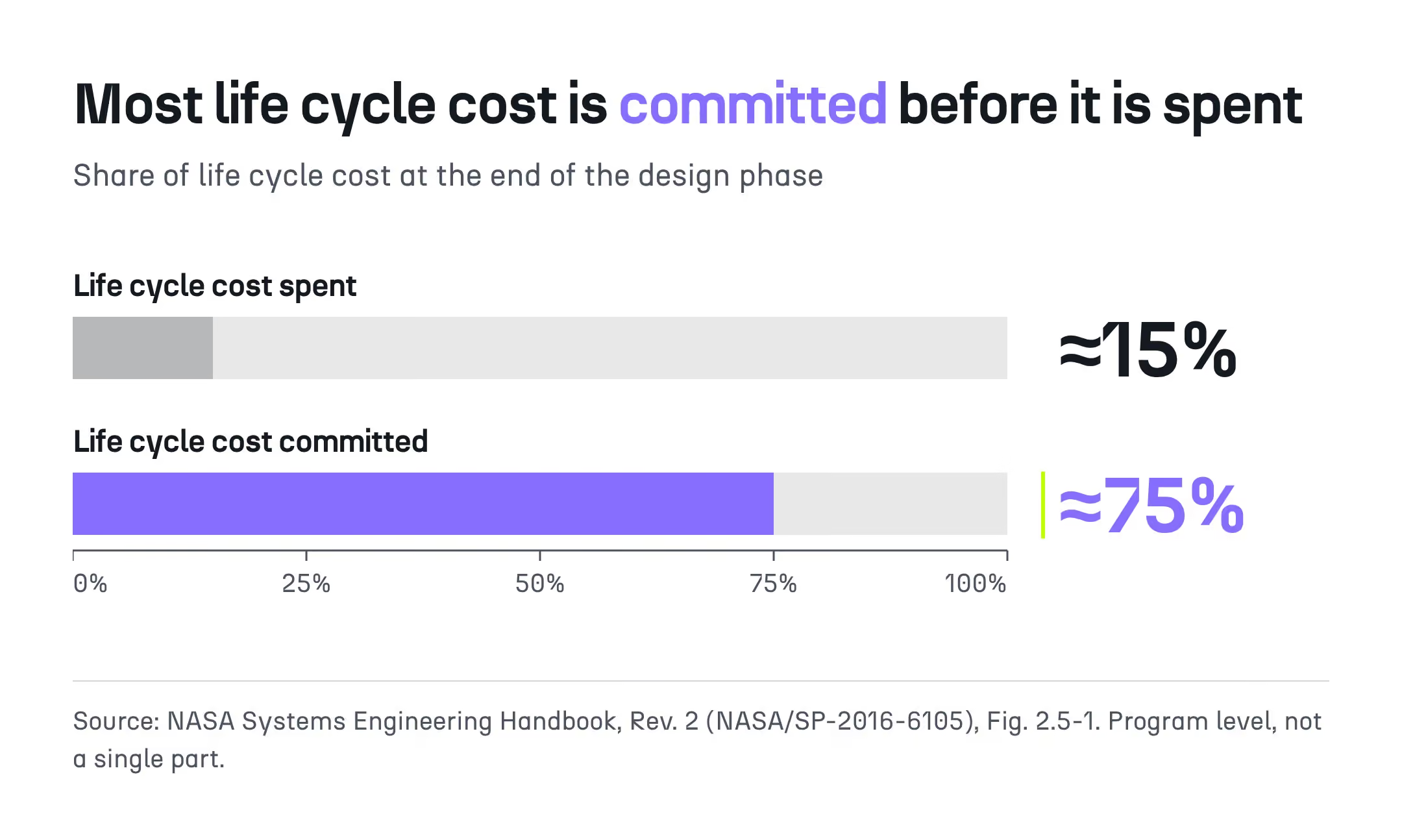
The timing matters because the concept phase is where most of a part's cost, mass and carbon footprint is decided. NASA reports that about 75% of life cycle cost is committed by the end of the design phase while only about 15% has been spent, which means that the least compared decisions of a program are also the most consequential.
This guide explains why DoE has stayed downstream, what now allows it to move upstream and how to run it, for design and mechanical engineers and for the managers who decide how a design office spends its time.
Concept decisions are taken with little comparison because each concept is expensive to evaluate. With a sequential loop of CAD modeling, meshing, simulation and manufacturing review, a design team can typically afford only a handful of candidates, and criteria such as cost or CO₂ arrive after the choice is made. The result is a paradox: the phase with the lowest cost of change is also the phase with the least exploration.
The economic side of this paradox shows in how program costs accumulate.
Material, manufacturing process, mass, part count and assembly sequence all follow from the selected concept, and later phases mostly refine that choice rather than revisit it. As a consequence, a correction made after the concept is frozen is paid at a much higher price: a NASA study of error cost escalation found that an issue costing 1 unit to fix at the requirements phase costs 3 to 8 units in design and 21 to 78 units in integration and test.
Industrial surveys confirm the pattern. In a study of more than 90 engineering companies, engineering changes absorbed almost one third of R&D capacity, and a 2025 CoLab survey of engineering leaders reports that 90% of them delay part of their product launches because of late-stage design changes.
Environmental impact follows the same logic. The European Commission estimates that up to 80% of a product's environmental impact is determined at the design phase, so a CO₂ estimate produced after the concept is frozen can confirm a choice but can no longer inform it.
Cost alone does not explain why so few alternatives are compared, because three mechanisms inside the design loop reinforce each other.
Each mechanism is rational on its own, which is why their combined effect goes unnoticed in design reviews:
Bain & Company estimates that engineers in aerospace and defense spend about half of their time on active engineering work, and that 30% or more of that time goes to rework. Engineering hours are therefore spent on the concept that already looks plausible rather than on alternatives not yet modeled.
The phase with the lowest cost of change is also the phase where the fewest alternatives are compared.
Design of experiments is a family of statistical methods for choosing which combinations of inputs to test, so that a limited number of runs reveals how the inputs affect the outputs. The method itself does not change at the concept phase. What changes is the content of each run, which becomes a complete concept generated and evaluated automatically rather than a dimensional variant of a frozen part.
The vocabulary of DoE transfers directly to concept exploration, provided each term is mapped to what an engineer actually controls at that stage.
A factor is an input that the plan varies, such as the starting layout or the volume target, and a level is a value that factor takes. A run is one combination of levels, which at the concept phase means one complete concept, and a response is a measured output such as mass, stiffness, peak stress, safety factor, manufacturability, cost or CO₂.
The choice of sampling plan then determines how many runs are needed and what can be learned from them.
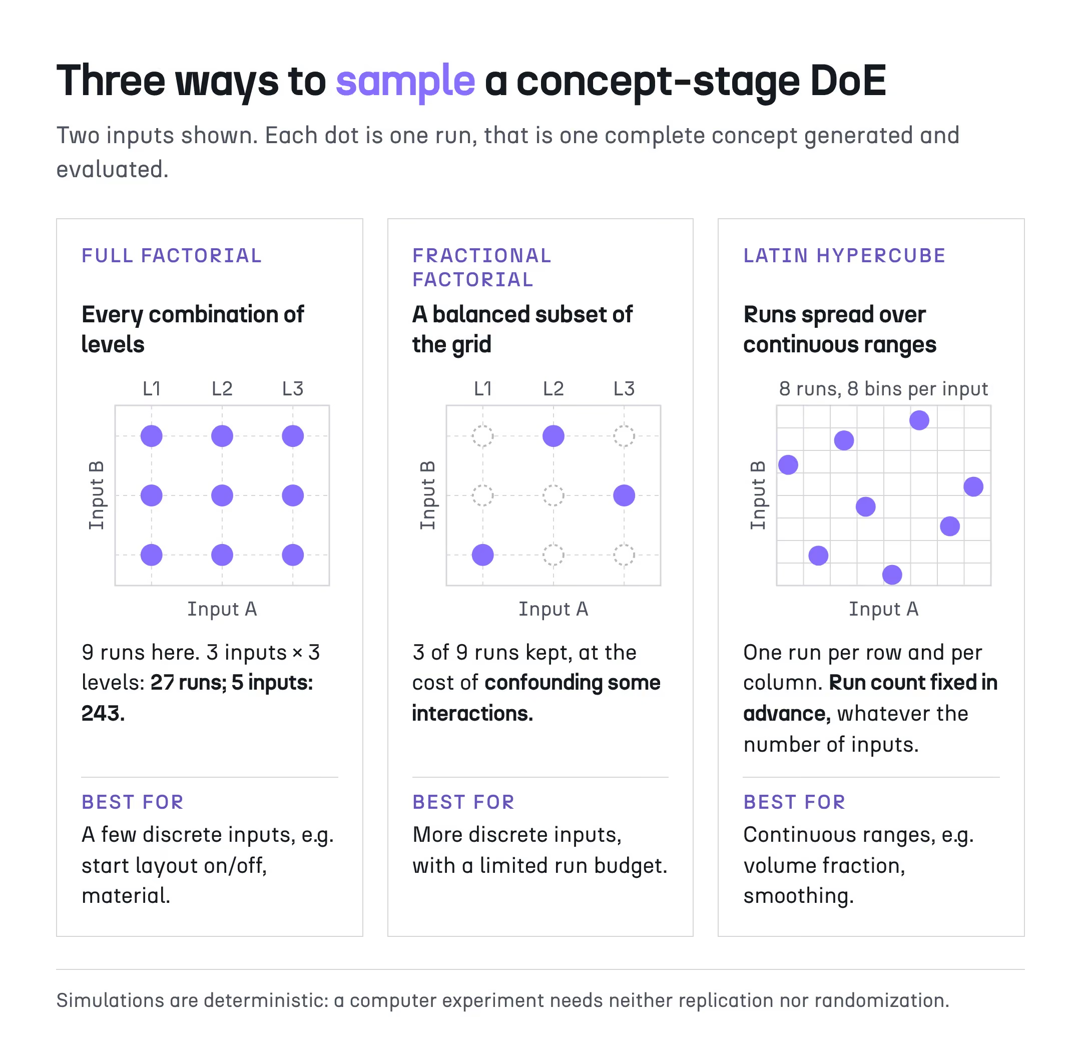
Full factorial designs test every combination and separate main effects from interactions, but their size grows quickly: three factors at three levels require 27 runs, and five factors require 243. Fractional factorial designs keep a balanced subset at the cost of confounding some interactions, while Latin hypercube sampling spreads a fixed number of runs evenly over continuous ranges.
Because simulations are deterministic, computer experiments need neither replication nor randomization. A few discrete inputs suit a factorial plan, while continuous ranges such as a volume fraction suit Latin hypercube sampling.
A parametric CAD DoE varies the dimensions of a frozen geometry to tune a part whose topology is already chosen. A DoE in the concept phase varies the inputs that generate the geometry, so two runs can belong to different topology families. The first answers how much a dimension matters; the second answers which type of part is appropriate, which is a different engineering question with different consequences.
In mechanical engineering, DoE is mostly applied at the detailed design stage, and this reflects a tooling limitation rather than a methodological choice. A feature-based CAD model rebuilds reliably only while its topology is unchanged, and each variant needs its own meshing and setup, so a systematic plan becomes affordable only once the concept is fixed.
The table below summarizes how the two approaches differ in what they vary, what they produce and what an engineer reads at the end.
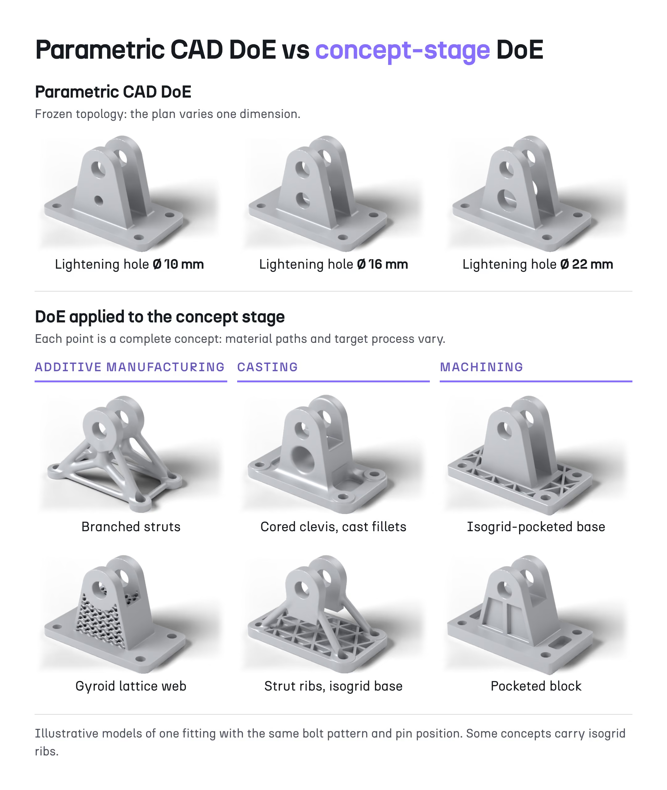
In the concept phase, relevant factors include inputs to geometry generation, materials, design space and load variants, and manufacturing constraint settings. The sweep is systematic, not exhaustive: it covers the ranges the engineer defines, and processes such as additive manufacturing, casting or machining are compared in separate workflows rather than ranked by the DoE itself.
A parametric CAD DoE asks how much a dimension matters. A concept-phase DoE asks which type of part is appropriate.
Topology optimization finds a good design near its starting point, on a limited number of objectives, which makes each run one sample of the design space rather than a map of it. The underlying problem is non-convex, cost and manufacturability usually sit outside the formulation, and the dense output often needs rebuilding in CAD before it can be assessed on criteria other than stiffness.
Each of these limits has a precise technical origin.
Gradient-based optimizers converge to the nearest local optimum, and level set methods, which move the part boundary described as the zero level of a function, depend strongly on the initial design. Generative design tools return several outcomes, typically one per material or process preset, but each outcome is still one run whose parameters the engineer did not plan as an experiment.
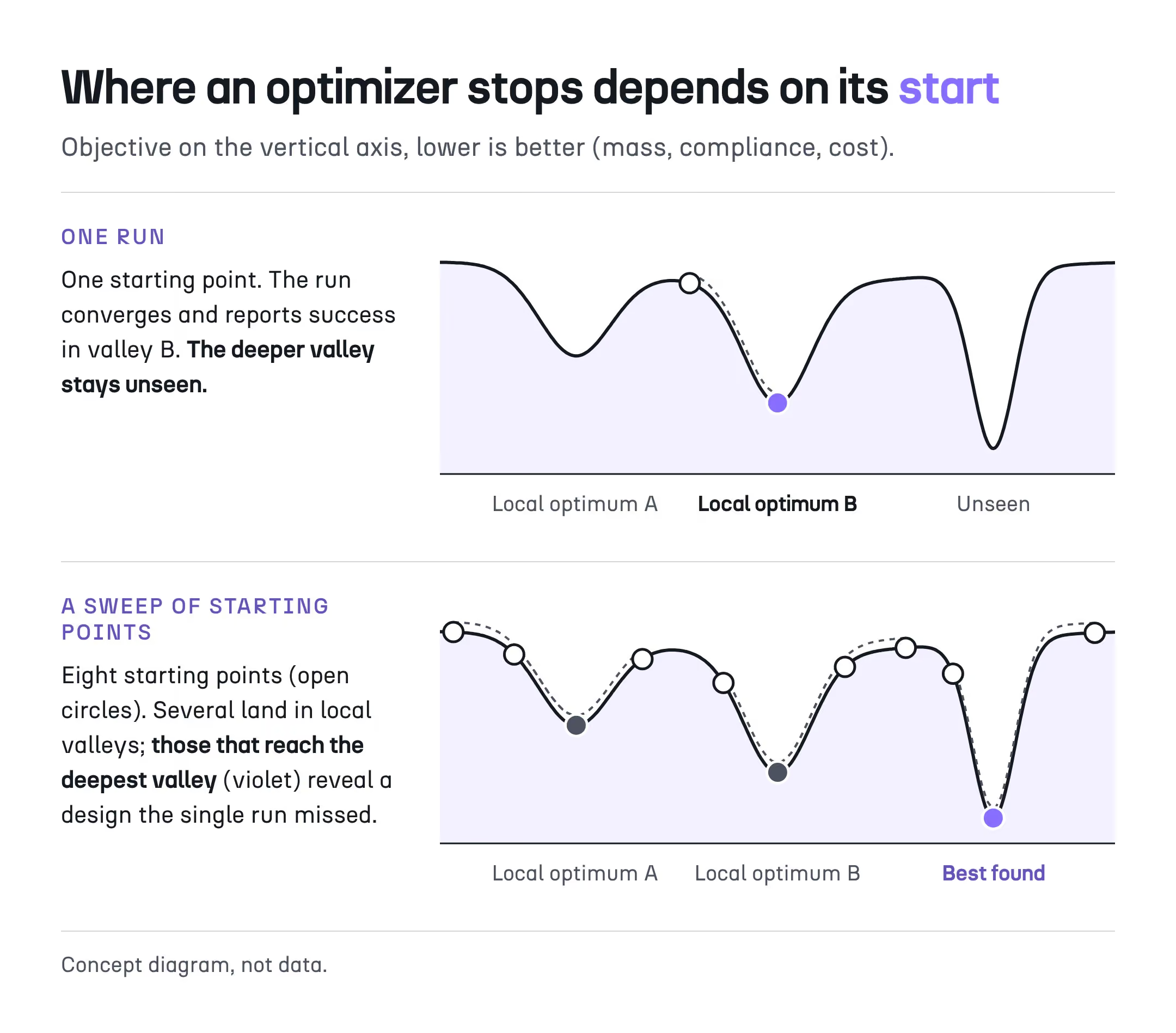
The formulation adds a second set of limits, on the criteria rather than the search.
The standard formulation minimizes compliance for a given volume, so cost, CO₂ and many manufacturing rules remain outside the optimization, and resolving a multi-objective Pareto front requires sampling the design space. The output is also a dense, faceted geometry: in a survey of 85 users, 49% cited a feature-based CAD model of the result as their first need, which means each concept carries a rebuild cost before it can be compared.
None of this makes topology optimization less useful. It means that, at the concept phase, a single run should be read as one sample, and that the value lies in running a plan of samples rather than in trusting one converged shape.
A concept-phase DoE is useful only if every run is automatic, robust, affordable and traceable. Two building blocks meet these conditions: implicit modeling, which keeps every generated concept a valid closed volume without CAD reconstruction, and a parametric design workflow, which applies the same chain from inputs to KPIs at every point of the plan without manual intervention.
The first building block concerns how the geometry is represented.
In implicit modeling, geometry is a scalar field over the volume rather than a set of surface patches driven by a feature history. Boolean operations and blends remain valid on organic shapes, holes and branches can appear or merge, and each concept is a closed volume that can be meshed and evaluated directly.
The second building block concerns how the evaluation is organized.
In a parametric design workflow, the chain from inputs to KPIs, covering geometry, analysis, manufacturability, cost and CO₂, is defined once and executed for every point of the plan. Every concept is therefore evaluated identically, each result traces back to its inputs, and the workflow can be reused on other parts of the same family.
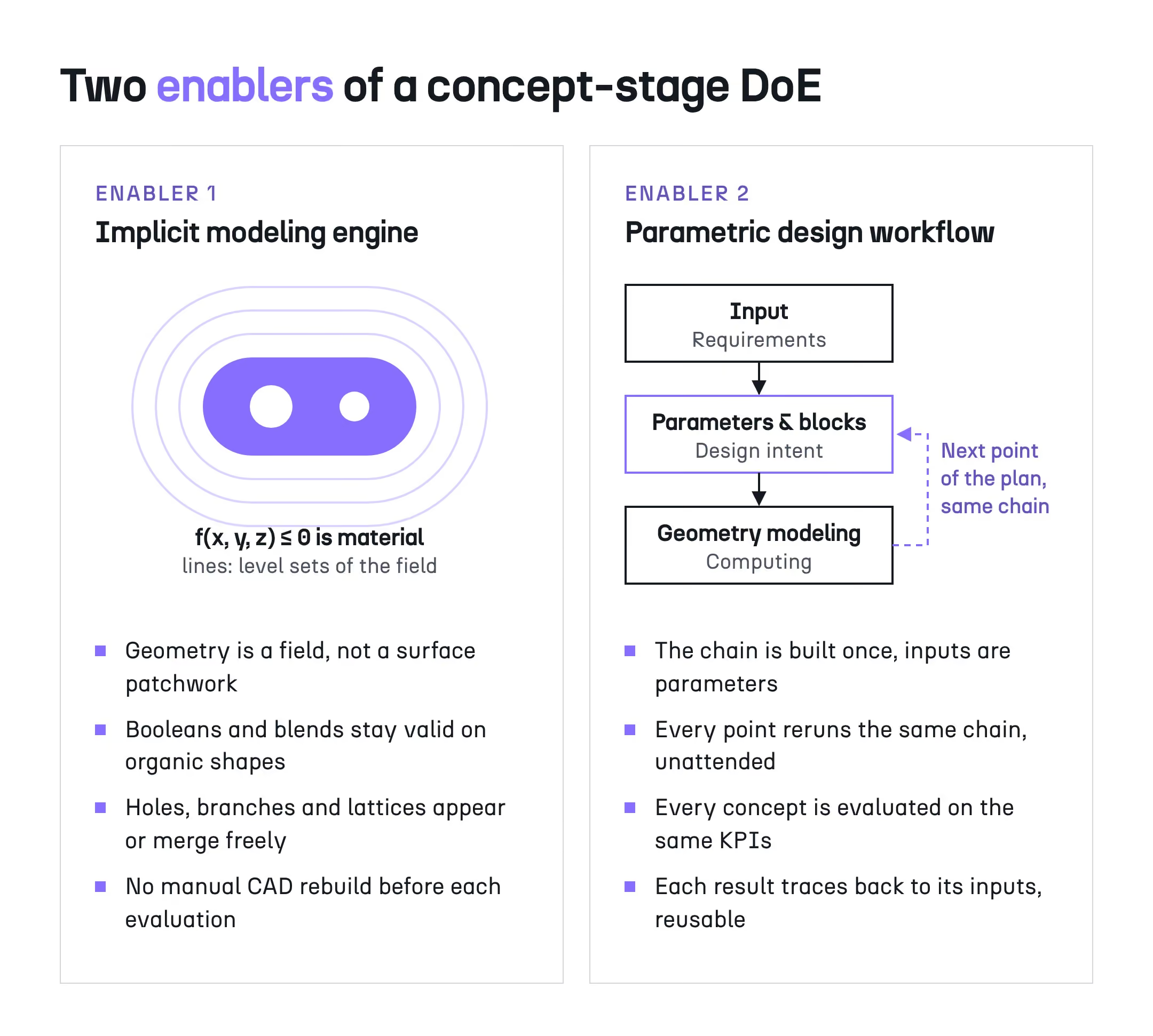
Together, these two building blocks change where the effort sits in the design loop.
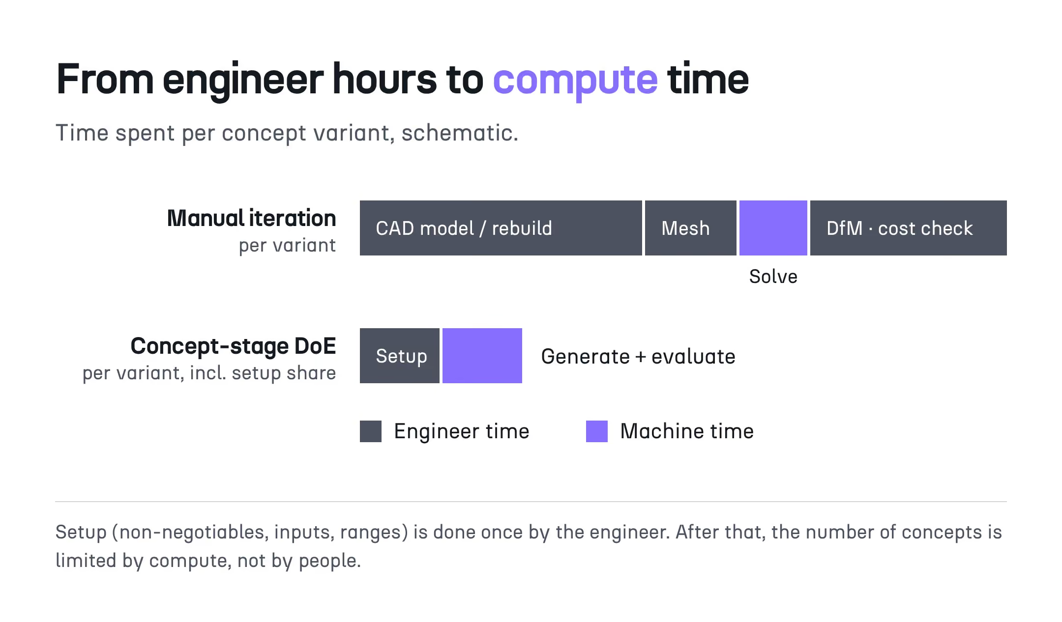
In a manual loop, effort grows in proportion to the number of concepts. In a concept-phase DoE, each variant costs minutes of compute and runs unattended, while the engineer's effort, setup before the sweep and review after it, stays nearly constant whether the plan contains 8 concepts or 80.
The trade-off is fidelity. Concept-phase evaluation needs to rank concepts correctly, not to certify them, so meshes and load cases are chosen for speed, and detailed CAE remains necessary on the selected concept before sign-off.
A concept-phase DoE follows seven steps: fix the non-negotiables, choose the inputs and their ranges, select a sampling plan, generate and evaluate each concept, collect the concept set, read it with multi-criteria tools, and decide on explicit criteria. The DoE produces the set; the selection remains an engineering decision, documented with the reasons for each rejected option.
The first three steps happen before any geometry is generated, and they deserve more attention than the sweep itself.
The engineer first fixes the non-negotiables: envelope, interfaces, keep-out zones, load cases, candidate materials, and a minimum safety factor or maximum displacement. The inputs that may change the topology, such as starting layout, volume target, smoothing or material, are defined next with their ranges, and a factorial or Latin hypercube plan is chosen according to whether those inputs are discrete or continuous.
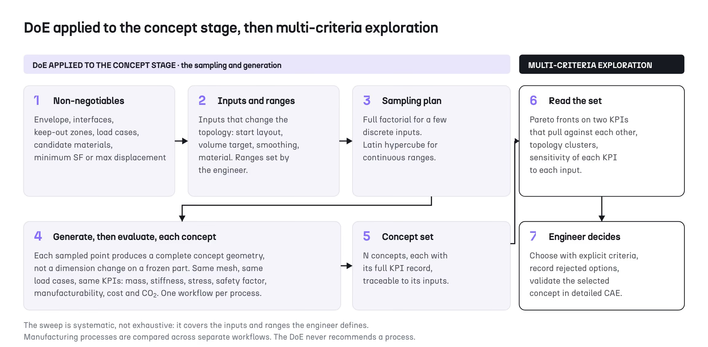
Once the plan has run, the engineer reads a set of concepts rather than a single design.
A set of 50 concepts described by six KPIs cannot be ranked visually, and three analyses usually provide most of the information:
The selection is then made on explicit criteria, rejected options are recorded with their reasons, and the chosen concept goes to detailed CAE. That record is what makes the decision auditable in later design reviews.
Comparing manufacturing processes follows the same logic, with one important rule.
Additive manufacturing, casting and machining impose different constraints, so each process gets its own workflow, and the resulting concept sets are compared side by side on the same KPIs. The DoE does not recommend a process: it shows what each process can achieve on the part, and the engineering team weighs those results against cost, supply chain and qualification constraints.
The same reasoning underlies concept-stage comparisons of additive manufacturing and CNC machining, such as the one documented in the Potez Aéronautique door bracket case study.
On a steel cantilever bracket, a Japanese industrial equipment manufacturer used a concept-phase DoE to understand why two optimizers returned different shapes. Thirty concepts, at about four minutes of compute each, showed that the starting layout selects the topology family, and that concepts of similar mass can differ by more than a factor of two in safety factor.
The starting point was a discrepancy that a single optimization run could not explain.
The team had optimized the same bracket with a density-based solver and with the level set method in Cognitive Design, and obtained two markedly different shapes. Because level set methods rarely nucleate new holes, the final topology depends on the initial layout, so the team swept the Start Design option, which seeds a grid of holes before optimization, together with the smoothing frequency, while keeping load case, material and volume fraction constant.
The sweep produced 30 concepts at about 4 minutes of compute per concept on a local workstation, roughly two hours in total. The CDS application team estimates a single manual iteration on a comparable part at about two hours, so 30 manual iterations would have required about 60 hours of engineer time.
Three observations came out of the set.
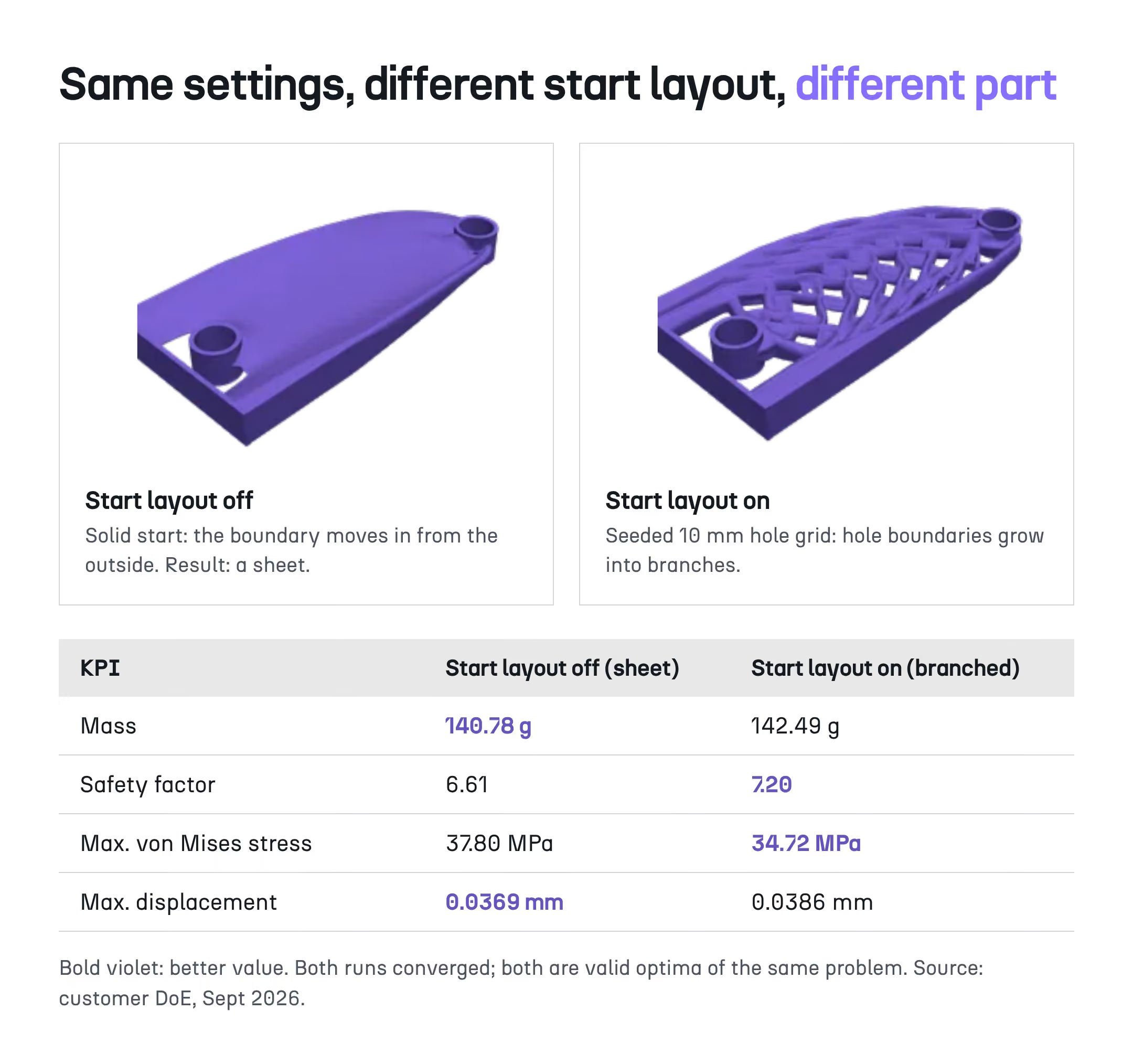
First, an organic shape does not imply better performance. With identical settings, seeding holes switched the topology from a sheet to a branched structure, which showed 8.1% lower peak stress and an 8.9% higher safety factor for 1.2% more mass, while the sheet deflected 4.4% less.
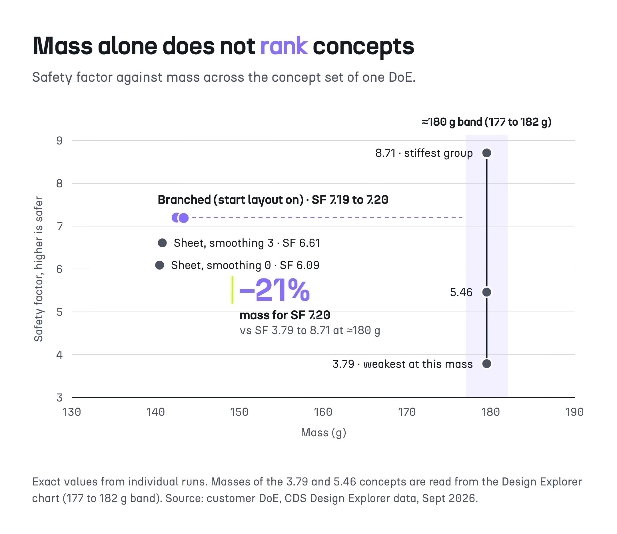
Second, mass alone does not rank concepts. At about 180 g, the safety factor ranged from 3.79 to 8.71, and the branched concept reached a safety factor of 7.20 at 142.5 g, about 21% lighter than the stiffest concept of that group.
Third, the initial layout selects the family and smoothing adjusts within it: in a 2 × 2 factorial, seeding holes raised the safety factor by 0.59 to 1.10, while smoothing raised it by 0.52 without seeding and by only 0.01 with it. These effects are specific to this bracket.
The customer finally retained the sheet concept, lighter and stiffer than the branched one, and validated it with its usual FEA tool. The DoE did not choose for the team; it showed what each family traded away, which is exactly the information a concept decision needs. The complete data set is available in the white paper on DoE at the concept stage.
The DoE did not choose for the team; it showed what each family traded away.
For engineering managers, a concept-phase DoE changes the variable that limits exploration: the constraint is no longer how many concepts a team can afford to model, but how many concept decisions are still taken without comparing alternatives. It also turns the concept choice into a documented, reusable decision rather than an individual judgment that leaves little trace for the next program.
Three effects matter at the level of a design office:
On a Thales Alenia Space part, an automated design workflow in Cognitive Design reduced the time per design variant from two weeks to two days, which indicates the order of magnitude at stake when generation and evaluation no longer depend on manual rework. Two indicators are worth tracking: concepts compared before freeze, and late engineering changes traced back to a concept choice.
A concept-phase DoE adds little value when the topology is already imposed, when only one or two inputs can change, or when the criteria that decide the design cannot be ranked with concept-level fidelity. In those cases, a parametric CAD DoE or a targeted high-fidelity study answers the real question more directly, at lower cost and with fewer assumptions to justify.
Heritage designs and parts constrained by an existing certification basis often leave no room for a different topology, and a dimensional study is then the honest tool. Similarly, when the governing criterion is fatigue life, crash behavior or a nonlinear contact problem that concept-level models cannot rank reliably, the sweep risks producing a confident ordering that detailed analysis would later overturn.
Setting up a workflow also has a cost: for a simple one-off part it may exceed what the exploration returns, whereas for a family of similar parts it pays back across every subsequent design.
Cognitive Design, the concept exploration software developed by CDS, includes a DoE panel since release 2.3. The engineer defines the parameters and their ranges, the software generates and evaluates every concept within those ranges with its implicit geometry engine, and the Design Explorer displays the resulting set for multi-criteria reading, with one workflow per manufacturing process being compared.
The sweep stays strictly within the parameters predefined by the engineer, and the existing capabilities, topology optimization, topology weaving, manufacturing-driven design and simulation-driven design, become the generators that the plan samples. More detail on the panel and its workflow is available on the Cognitive Design DoE page.
Design of experiments was kept downstream for a sound reason: as long as each concept took hours to rebuild and check, a systematic plan was out of reach at the concept phase. Once generating and evaluating a concept becomes a matter of compute, the relevant question is no longer which optimizer performs best, but when the comparison takes place and on how many criteria.
The guide to manufacturing-driven design explains how process constraints enter the generation phase, and the article on lightweighting a part without losing stiffness details the trade-offs that a concept set makes visible.
Explore our frequently asked questions to understand how our software can benefit you.
Design of Experiments is the method of systematically sweeping input parameters, such as geometry variables, materials, and manufacturing processes, to populate a design space with candidate variants, each of which is then evaluated against the same KPIs.
Topology optimization searches for one good design near its starting point, usually on stiffness for a given volume. A DoE samples the inputs of that search systematically, so the engineer sees how results change across starting layouts, settings, materials or processes. The two are complementary: the optimizer generates concepts, and the DoE organizes which ones are generated.
It depends on the number of inputs and the sampling plan. Three factors at three levels require 27 runs in a full factorial plan, while Latin hypercube sampling uses a fixed budget over continuous ranges. In the industrial bracket case described in this guide, 30 concepts were enough to explain the difference between two topology families.
Yes, provided each process has its own workflow with its own constraints, for example additive manufacturing, casting and machining. The concept sets are then compared on the same KPIs. The DoE shows what each process can achieve on the part; it does not recommend a process, which remains an engineering and supply chain decision.
No. A concept-phase DoE is systematic, not exhaustive: it covers the inputs and ranges that the engineer defines before the sweep. The quality of the result therefore depends on the choice of requirements, factors and ranges, which deserve more attention than the sweep itself.
Concept-phase evaluation needs enough fidelity to rank concepts correctly on the criteria that govern the design, not to certify them. Meshes and load cases are chosen for speed, and the selected concept is then validated with detailed CAE before sign-off. When the governing criterion cannot be ranked at that fidelity, a targeted high-fidelity study is more appropriate.
Once the workflow is set up, each concept costs minutes of compute and runs unattended. In the bracket case, 30 concepts took about two hours at roughly four minutes each, whereas a single manual iteration on a comparable part takes about two hours of engineer time, or about 60 hours for 30 iterations.
Mass, stress, safety factor, cost, CO2, and manufacturability are the core KPIs, evaluated concurrently on every candidate variant rather than checked sequentially after a geometry has already been selected.
For a derivative part with minimal design freedom, such as a single interface dimension change on an already-qualified bracket, the upfront cost of defining a full design space and running a Design of Experiments sweep can exceed the benefit of a direct, targeted modification.
No. A concept-phase DoE helps choose the type of part on several criteria before the concept is frozen. Dimensional tuning, a parametric CAD DoE and detailed CAE remain necessary afterward to refine and validate the selected concept. The two methods answer different questions at different stages of the same program.

Request a demo to see how Cognitive Design by CDS can revolutionize your engineering workflow