Henri De Charnacé
CTO
Last updated: August 2026
Concept exploration promises geometric freedom: dozens of generated design variants where a manual workflow produced two or three. Manufacturing-driven design (MDD) is the methodology that protects that freedom by evaluating manufacturing process constraints, and the choice of the manufacturing route itself, concurrently with mechanical performance during concept generation, rather than at a downstream design-for-manufacturing (DFM) gate.
The distinction sounds procedural. In practice it decides whether the concepts a team compares are genuine options or provisional sketches, because a variant that violates the rules of its manufacturing process was never a real candidate, however well it performs structurally. This guide examines how MDD differs from traditional DFM review, what changes when process constraints enter the concept exploration stage, how manufacturing routes can be compared before geometry is committed, and where the methodology honestly trades against lightweighting performance.
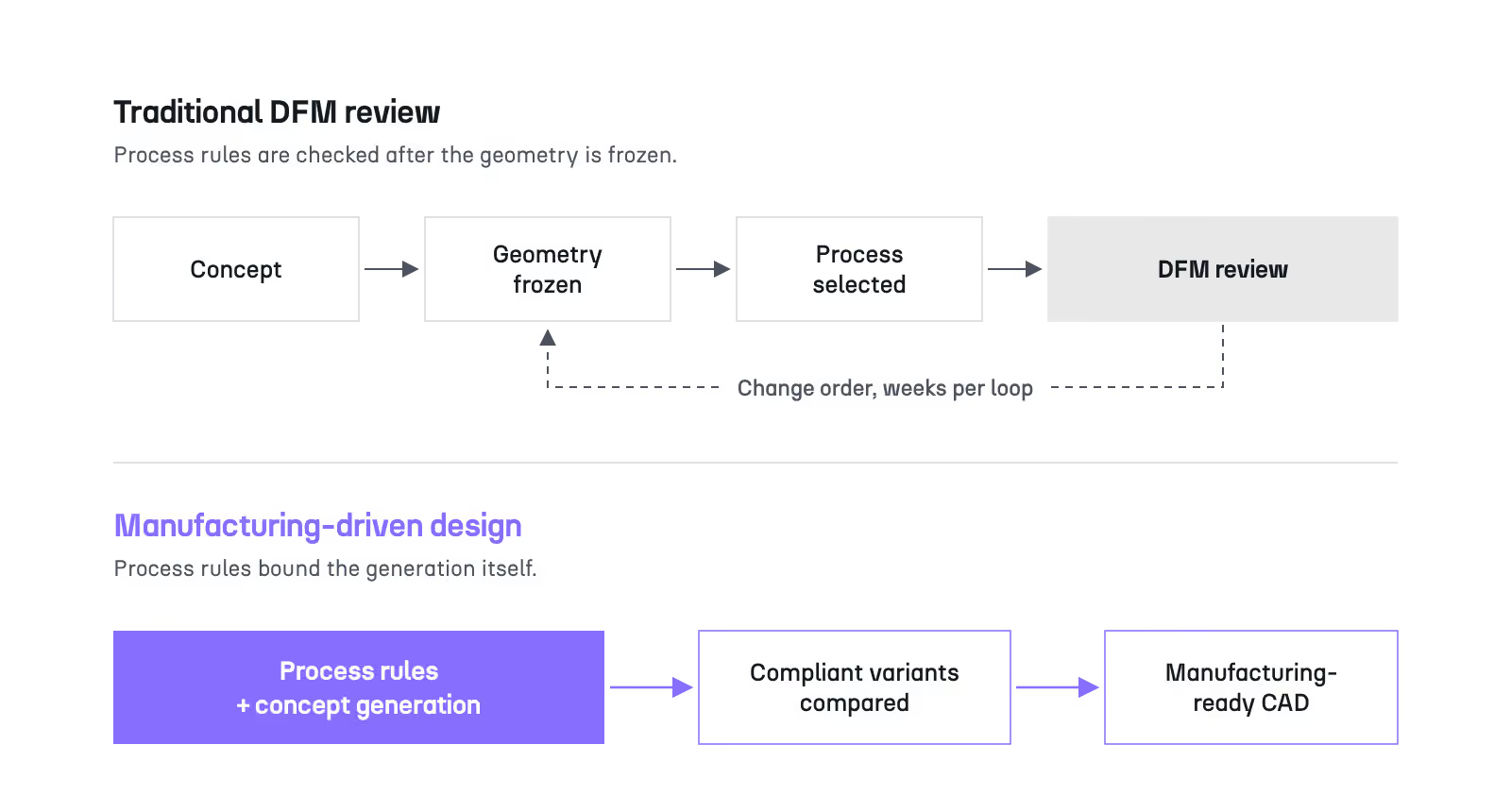
Traditional DFM review validates a design after its geometry and manufacturing process have been selected, which turns every manufacturability finding into a change order against committed work. Manufacturing-driven design applies the same process rules during concept generation, so geometry and process are explored together before either is locked. The checks themselves barely change: draft angles, overhangs, wall thickness, tool access. What changes is their position in the workflow, and therefore the cost of acting on them.
The most common configuration deserves a precise description, because its cost structure explains why the alternative exists.
In a gated workflow, the design office converges on a geometry, selects a process, and only then submits the result to manufacturing review. Any non-compliant feature discovered at that point, an undercut the die cannot release, a wall the mold cannot fill reliably, a pocket the cutter cannot reach, must be corrected against a design the team has already validated structurally and often already discussed with suppliers.
The economics of that timing are unforgiving. A constraint violation caught during concept work costs a few hours of regeneration; the same violation caught after tooling is engaged can mean a modified or scrapped die, a requalification loop, and a renegotiated supplier schedule, a correction that routinely reaches tens of thousands of euros on regulated programs. This asymmetry explains why aerospace programs keep redesigning the same parts late in the cycle: the review that could have prevented the redesign ran after the decisions it needed to influence.
The organizational symptom is easy to recognize. The manufacturing engineer joins the program at the tooling gate, as an approver of finished work, instead of at concept kickoff, as a contributor of constraints.
Between the pure gate and true constraint embedding sits a third configuration, and it is where most engineering teams actually operate.
Many organizations consult a manufacturing engineer early, in a kickoff meeting or an informal design review, and consider DFM handled. The conversation produces guidance: keep walls above a threshold, avoid undercuts on a given face, place the parting line here. What it does not produce is a mathematical boundary on the geometry that will be generated afterward.
This middle case behaves like traditional DFM in practice, because the optimization that shapes the concept still runs unconstrained; the guidance lives in meeting notes rather than in the design space definition. When the generated geometry drifts outside what was discussed, the drift is discovered exactly where it would have been without the meeting: at review, after commitment.
Naming this pattern matters because it is the honest starting point for most teams. Moving from informal consultation to manufacturing-driven design is not a matter of talking earlier. It is a matter of encoding what is said.
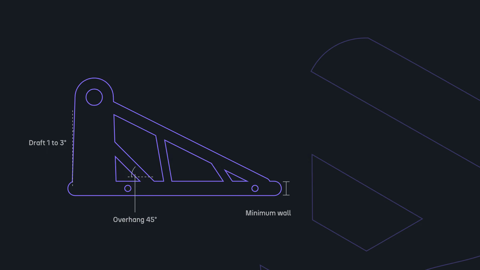
When manufacturing constraints enter the concept stage, they stop being review criteria and become boundary conditions of the design problem. Rules such as draft angle, parting line placement, overhang angle, and wall thickness are encoded as mathematical constraints of the optimization itself, so every generated candidate is either born compliant with its target process or carries an identified non-compliance status from the moment it exists. And because no process is committed yet, the same rules can serve a second purpose: variables to compare across candidate manufacturing routes rather than settings calibrated for a single one.
The first shift concerns how the design space is defined before any variant exists.
In a process-first definition, the constraint set of the target process enters the problem formulation alongside loads and interfaces. For die casting, that typically means draft angles of 1 to 3 degrees per pull direction and near-constant wall thickness; for metal additive manufacturing, self-supporting angles commonly capped around 45 degrees and minimum feature sizes on the order of 0.5 to 1 mm depending on machine and alloy; for 5-axis machining, a tool accessibility envelope that excludes unreachable internal volume.
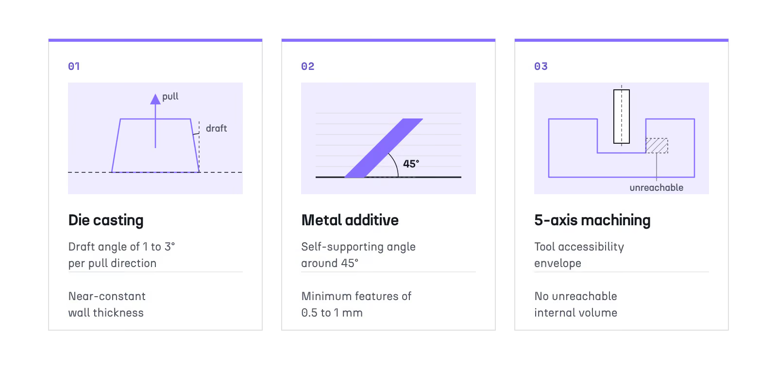
Set as global constraints from the start, these rules do not filter variants after generation; they bound what generation can produce. Every candidate is born compliant, or is flagged as non-compliant the moment it is created, which changes the nature of the downstream comparison: choosing among variants becomes choosing among buildable variants.
The second shift concerns what those constraints are for at this specific point in the program.
Concept stage is the last moment when the manufacturing route is genuinely open, and a manufacturing-agnostic starting posture is only useful if it converges through evidence. At this stage, draft angle, parting line, overhang, and thickness are not settings to calibrate for one chosen process; they are the defining variables of alternative versions of the same part, one per candidate route, that deserve to be tested against each other.
Once a route is locked in, the work changes character: the relevant questions become parameter-level mechanics, exact overhang values, minimum feature sizes, refinement settings, which belong to the discipline of topology optimization itself rather than to route selection. Manufacturing-driven design earns its value in the window before that lock, when the comparison is still real.
A process trade study at concept stage runs one generation pass per candidate manufacturing route, each bounded by that route's own rules, and compares the resulting variants in a single decision environment on identical criteria: mass, unit cost including tooling amortization, CO2, and manufacturability status. It is a comparison of parallel runs, not a simultaneous multi-process solve, and it remains a leading-edge practice rather than an industry default.
The mechanics of that comparison are worth spelling out, because they differ from simply quoting one geometry across several suppliers.
Each candidate route gets its own generation pass: a forging-plus-finish-machining pass bounded by forgeability considerations, a billet-machining pass bounded by tool access, a casting pass bounded by draft and wall uniformity. The passes share the same loads, interfaces, and performance targets, but each produces geometry shaped by its own process, which is the only fair basis for comparison; quoting a machining-shaped geometry to an additive supplier silently biases the answer toward machining.
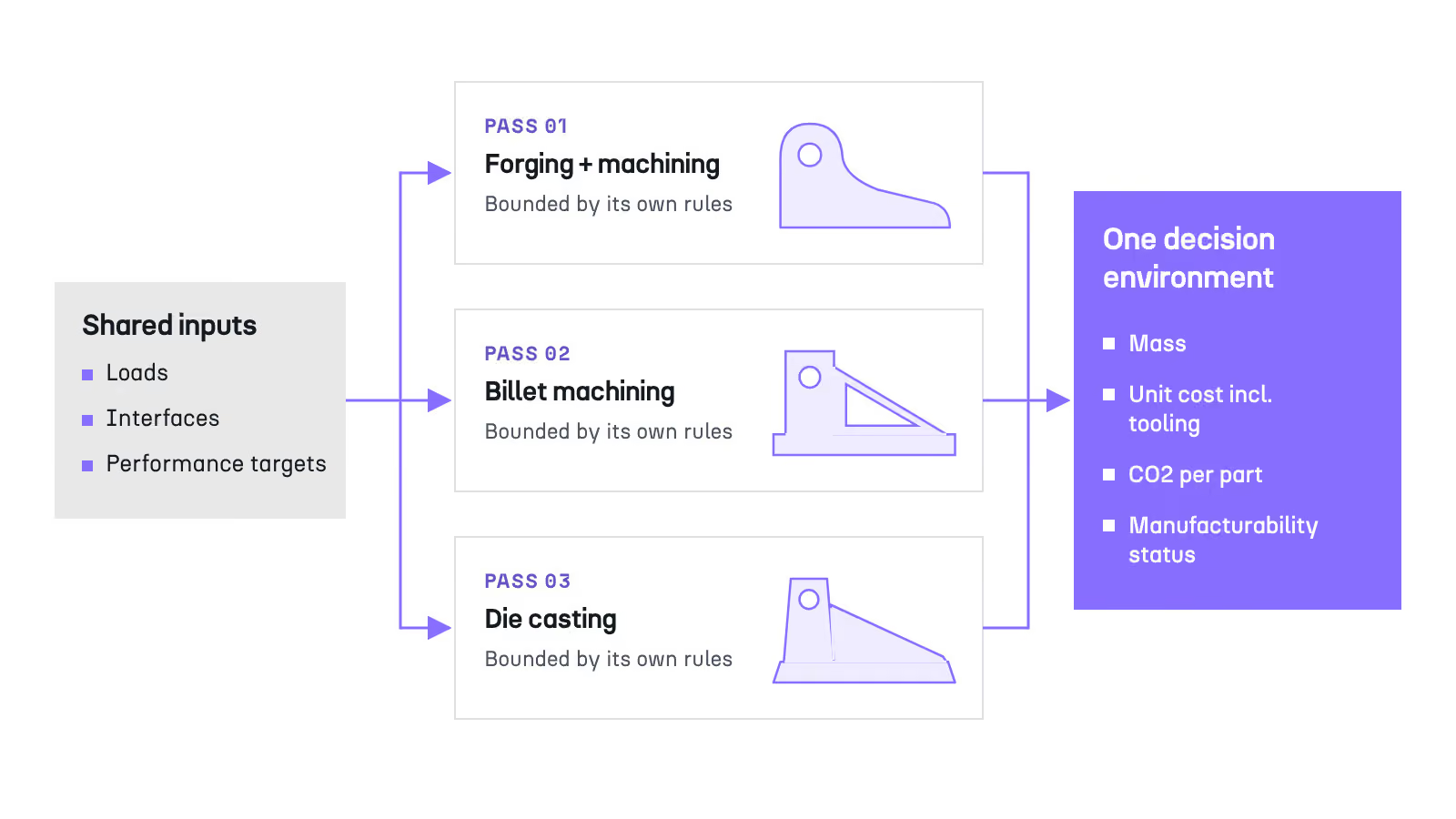
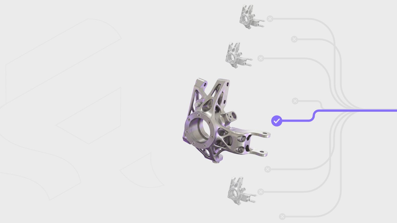
The resulting variants then land in one decision environment and are scored on the same criteria. As a concrete illustration of the approach, an aerospace bracket study compared three candidate manufacturing routes under six concurrent load cases before any geometry was committed.
Honesty about adoption is due here: this remains a leading-edge practice. Most organizations still default to whichever process the last similar part used, not because the comparison lacks value, but because running it manually across processes has historically been too expensive to justify.
What the routes are scored on matters as much as how the passes are run.
Four criteria carry a concept-phase trade study: mass, unit cost including tooling amortization, CO2 per part, and manufacturability status against the route's rules. Tooling amortization deserves emphasis, because it is what keeps the cost comparison honest across routes: a die-cast part that looks inexpensive per unit carries its tooling in the denominator, and the ranking flips depending on production volume.
One limit should be stated plainly. At concept stage, structural evaluation rests on linear structural and thermal analysis, so fatigue life and forging grain-flow performance stay outside the scoring; decisions that hinge on them require dedicated downstream analysis on the selected concept. A trade study that claimed to settle fatigue at concept stage would be overreaching.
The table below summarizes how the four main route families typically compare on the criteria that drive a concept-stage decision.
CriterionAdditive (metal PBF)Casting (die)ForgingMachining (5-axis)Typical lead time to toolingNo dedicated tooling; first parts in days to weeksTooling typically 8 to 16 weeksDies typically 10 to 20 weeksFixturing only; days to weeksRelative unit cost at volume (tooling amortized)High; weak economy of scaleLow once tooling is amortizedLow to moderate at volumeModerate to high; scales almost linearlyGeometric freedomHighest; internal features and latticesModerate; draft and near-uniform walls requiredLow; simple forms with finish machining expectedHigh externally; limited by tool accessBest-fit production volumePrototypes to roughly 1,000 partsRoughly 10,000 parts and aboveRoughly 1,000 parts and aboveOne-offs to roughly 10,000 parts
A manufacturing-agnostic topology optimization will always find a lighter theoretical result than one constrained to a buildable process, because draft angles, minimum wall thickness, and support volume all remove usable design space. Manufacturing-driven design therefore trades some theoretical mass reduction for a part that is actually buildable at the chosen process and volume. The workflow friction of DFM review disappears; the physics of the achievable optimum does not.
That trade-off deserves to be examined directly rather than implied away.
Documented industrial topology optimization projects report mass reductions ranging from roughly 30% on heavily loaded parts to 60% on parts redesigned without legacy constraints, and the unconstrained mathematical optimum always sits above the constrained one for the same load set. Every process rule is a subtraction from the design space: a draft angle forbids vertical walls the optimizer would otherwise choose, a minimum thickness forbids the thinnest members, a self-supporting angle forbids the most efficient overhanging strut.
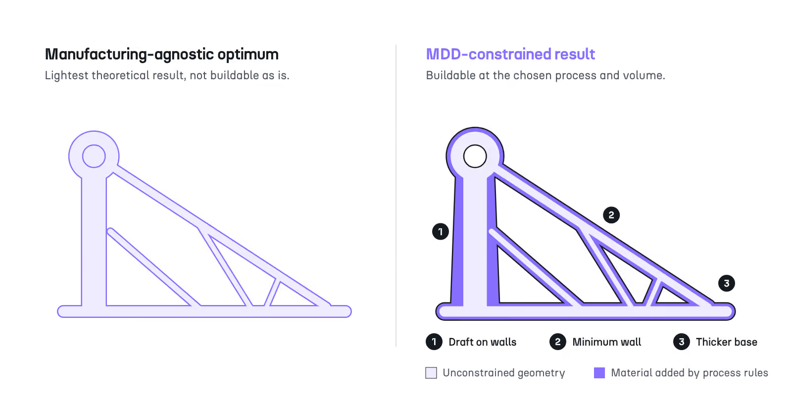
Manufacturing-driven design accepts that subtraction deliberately. The constrained result gives back part of the theoretical reduction in exchange for being the version of the part that can exist at the chosen process and production volume, and lightweighting a part without losing stiffness is only meaningful within that buildable space. Stating the exchange plainly is what separates an engineering methodology from generic promotion.
Acknowledging the trade-off raises an apparent contradiction with a promise frequently attached to MDD, and the two claims are worth reconciling explicitly.
The promise of eliminating DFM back-and-forth refers to review-cycle friction: send the design to manufacturing, receive a rejection, redesign, resubmit. That loop, with its weeks of latency per cycle, is what constraint embedding removes, because there is no non-compliant geometry left to reject.
The promise does not refer to the physics of the achievable optimum, which stays bounded by real process constraints no matter when they are applied. Both statements hold at once: the workflow friction disappears, and the achievable mass reduction remains bounded. Presented together they are more credible than either claim alone, and together they describe what lightweighting in production programs actually looks like.
Cognitive Design implements manufacturing-driven design by integrating post-process design data, DFM rules, cost, and manufacturability, into a generation phase whose primary objective is structural performance: the best achievable compromise between lightweighting and stiffness for a given design space and load cases. The selected process's rules apply during generation through the Manufacturing Analysis node, and every generated variant reaches the comparison stage carrying its full KPI set.
The way that integration is built reflects a specific view of where manufacturing data belongs.
Generation in Cognitive Design is first a performance engine: a compliance-driven optimization that seeks the best achievable lightweighting and stiffness compromise for the defined design space and load cases. The platform's design philosophy is to bring into that engine the design data that traditionally belongs to post-process: the DFM rules of the selected process, cost, and manufacturability.
Instead of a performance-optimized geometry meeting its process constraints downstream, the optimizer converges directly toward geometries that are light, stiff, and buildable, with the Manufacturing Analysis node as the concrete mechanism of that integration: the process is selected upfront, and its rules apply while the geometry takes shape, not after.
The practical consequence is that manufacturability questions are settled while a correction costs hours of regeneration rather than tooling budget, and industrialization receives a geometry already verified against its process: the DFM back-and-forth leaves the workflow because its object no longer exists.
On the Potez Aeronautique Falcon 6X structural bracket, the concept-to-manufacturing-ready-CAD cycle compressed from 192 hours to 28 hours, an 85% reduction in engineering lead time. The handoff itself stays standard: the selected concept exports through STEP or IGES into the existing CAD stack, with no tool migration and no retraining of the CAD team.
Manufacturability is one criterion among several. Each concept session generates 50 to 100+ variants through a Design of Experiments sweep, and every variant lands in the Design Explorer with its full KPI set attached: mass, structural performance through stress, displacement, and safety factor, unit cost, CO2 footprint, and manufacturability score.
The selection that follows is the point of the whole methodology. The engineer does not pick a manufacturable geometry; they pick the best multi-criteria trade-off among dozens of manufacturable options, with the reasoning behind the choice documented by the exploration itself.
Manufacturing-driven design displaces two habits at once: DFM moves from a gate at the end of design to a criterion inside generation, and the manufacturing route moves from an inheritance of the last similar part to the outcome of a compared trade study. Neither displacement makes parts lighter than physics allows; both make the parts that reach production the ones that were actually compared.
To go deeper on adjacent methodology, see how optimized geometry becomes usable CAD, how reusable engineering workflows carry these constraint sets across part families, and what a structured concept exploration phase looks like end to end. To evaluate your own workflow against the practices described here, download the Manufacturing-Driven Design checklist.
Explore our frequently asked questions to understand how our software can benefit you.
Manufacturing-driven design is a methodology that evaluates manufacturing process constraints, and the choice of the manufacturing route itself, concurrently with mechanical performance during concept generation. Process rules act as boundary conditions of the design problem rather than downstream review criteria, so every generated concept is manufacturable by construction instead of being validated after the fact.
DFM is a body of process rules; traditional DFM review applies them after geometry and process are fixed. Manufacturing-driven design applies the same rules mathematically during generation, before either is committed. The checks are largely identical; what changes is their timing, and therefore the cost of acting on what they find.
At design space definition, before the first variant is generated. Draft angle, parting line placement, overhang angle, and wall thickness limits should enter the optimization as global constraints, so manufacturability shapes the geometry from the first iteration instead of filtering candidates after generation.
No. Constraint-bounded generation runs at the same pace as unconstrained generation, and a process trade study runs as parallel passes within the concept phase. The setup time it adds upfront is small compared with the review cycles and tooling-stage redesigns it removes downstream.
Yes, as parallel generation passes: one pass per candidate route, each bounded by that route's own rules, with the resulting variants compared side by side in a single decision environment on identical criteria. It is a comparison of parallel runs, not one simultaneous multi-process solve.
A manufacturing-agnostic optimization will always find a lighter theoretical result, because process rules remove usable design space. Manufacturing-driven design trades part of that theoretical mass reduction for a geometry that is buildable at the chosen process and volume, which is the version of the part that actually reaches production.
No. The methodology applies wherever a process imposes geometric rules: draft angles and parting lines for casting and molding, tool access for machining, forgeability rules for forging, overhang and feature-size limits for additive manufacturing. Its comparative value is highest precisely when several of those routes are plausible for the same part.

Request a demo to see how Cognitive Design by CDS can revolutionize your engineering workflow