
Henri De Charnacé
CTO
.avif)
Consider a common transition in engineering organizations: an engineer with a decade of experience across several major aerospace programs leaves the company. Access credentials are revoked and files are archived according to standard procedure. The immediate concern is typically the preservation of design data: CAD models, simulation setups, and validated material libraries. Yet the more substantial loss lies elsewhere.
What accompanies the departing engineer is not primarily data but judgment, the accumulated set of decisions on sequencing, constraints, and design targets developed over years of practice. Geometry can be reconstructed from archived files. The reasoning process that produced it reliably, to certification-grade standards, generally cannot. This pattern recurs systematically across aerospace, automotive, and industrial manufacturing programs. Organizations tend to treat it as an unavoidable operational cost. The evidence suggests otherwise.
This guide examines what a reusable engineering workflow is, and the challenges in engineering organizations it is built to address.
A reusable engineering workflow is a parametric, rule-encoded sequence of design, simulation, and manufacturability steps. It can be re-run on a new geometry or requirement set without rebuilding the underlying logic from scratch. It captures the load cases, the preservation zones, the material rules, and the validation criteria an engineer would normally apply from memory. That logic gets packaged as a portable asset, not a one-time configuration. Change the input geometry, and the workflow reconfigures itself around the new constraints instead of requiring a manual rebuild.

The distinction matters because most engineering teams already have templates, standard operating procedures, and shared CAD libraries. None of those capture decision logic: which boundary conditions apply, which constraints are hard limits, and which trade-offs are negotiable. A reusable workflow does, and that is what separates it from ordinary documentation.
The operating principle behind this approach comes down to three steps: build once, reuse instantly, share indefinitely. Build once means investing an experienced engineer's time to define the design space properly, including optimization targets, manufacturing constraints, and validation thresholds. Reuse instantly means a new project with similar geometry deploys the same workflow in days or hours, not weeks. Share indefinitely means the configuration can be packaged and handed to any engineer on any team, who inherits the logic without a handover meeting.
In a typical CAx environment, this looks less like a single script and more like a layered configuration. Boundary conditions, material assignments, and manufacturability checks all live inside it, tagged to the part class rather than to one geometry. An engineer opens the workflow, points it at a new STEP file, and lets the encoded logic run the first pass. None of that removes engineering judgment. It moves that judgment upstream, into the one-time act of building the workflow, instead of repeating it on every part that follows.
Workflow amnesia is the systematic loss of engineering decision logic that happens when a project ends, a team restructures, or a senior engineer leaves. Legacy CAD and CAE tools capture what was designed in exhaustive detail. They stay blind to how and why a design reached its final form. PLM systems compound the problem: they version geometry and configuration in detail, but never version the reasoning behind a decision. The result is a structural loss that resets with every program, every team change, every departure.
In practice, that logic lives in one of three places: the engineer's head, an old email thread, or a handover document nobody reads twice. The sequencing behind topology optimization, the manufacturing rules, the validation criteria: none of it survives the handoff in a form anyone can reuse.
A PLM system will tell you which revision of a bracket shipped last quarter. It will not tell you why the engineer chose a 1.5g margin over a 2g margin on that specific interface.
This pattern gets worse at scale. Every new program re-learns what the last one already knew, and every new engineer reconfigures from scratch what a predecessor spent months perfecting. "The geometry can be recreated. The process that produced it reliably, and to certification-grade standards, is what's gone."
In regulated industries, where certification demands traceable and repeatable processes, workflow amnesia is not just inefficient. It is a structural vulnerability, and it resurfaces on every new program.
The configuration trap is the recurring cost of treating every part variant as a new problem, even when the underlying engineering logic barely changes. It shows up in two places: rebuilding a CAD and CAE configuration for every part in a family, and comparing results by hand across every variant explored. On a 20-variant bracket family, rebuilding alone can add roughly 40 engineer-weeks of overhead before a single final decision gets made. On the exploration side, comparing fifty candidates manually can take longer than generating them in the first place.
Mechanical brackets illustrate this well. They are high-volume and structurally critical, yet endlessly varied in geometry, while the underlying engineering logic across a family stays remarkably consistent. Under the current model, each variant still gets treated as a unique problem: topology targets re-entered, manufacturing rules re-applied, material envelopes re-specified.
The math holds up at scale. A traditional configuration cycle runs roughly two weeks per part. Across a 20-variant family, that adds up to about 40 engineer-weeks of overhead before a single final design decision gets made. A reusable workflow collapses that overhead to the initial build plus a fraction of the time per subsequent variant, since the class-level logic already exists. Thales Alenia Space saw the same pattern on its 80+ variant antenna bracket family: 2 weeks per part down to 2 days, a 7x acceleration.
.jpg)
The same trap shows up on the exploration side, even outside a defined part family. Generating fifty candidate variants by changing a single parameter can take an afternoon. Comparing them by hand, across mass, stress, cost, and manufacturability, routinely takes longer than generating them. What starts as an afternoon of exploration can stretch into a week of spreadsheet work.
Two failure modes follow from this:
This is the configuration trap. A team keeps re-buying knowledge it already purchased once, one bracket or one design iteration at a time, without ever noticing the bill.
Building a reusable workflow means defining the optimization strategy at the class level, the level of the part family, instead of the individual part. Three layers get encoded once: the design space and load cases, the manufacturability rules per process, and the validation criteria. Once that class-level logic exists, a new part geometry gets imported and the workflow adapts around it, instead of triggering a manual rebuild.
Each layer plays a specific role:
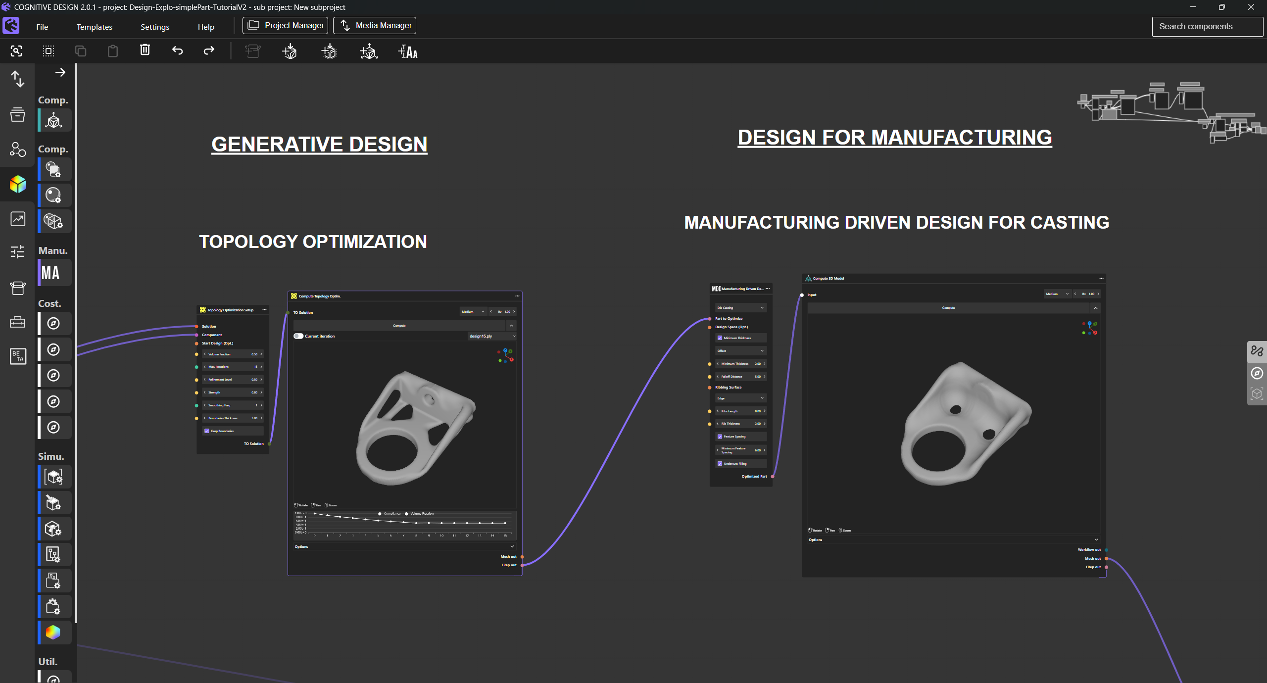
The benefit becomes apparent the moment a new geometry enters the picture. Load cases scale to the new dimensions. Manufacturing constraints stay valid, since they were defined at the family level, not the individual part level. The optimization runs without a manual rebuild step, and engineering time shifts from re-entering constraints to reviewing results.
The table below summarizes the practical difference between the two approaches.
Because the reasoning behind every parameter gets recorded, the resulting asset is auditable, not just convenient. The same inputs always produce the same outputs, and that matters directly for programs that need a traceable evidence base for certification.
Reusable workflows create value in three distinct contexts, and only the first is about part families directly. The second is design exploration. Changing one parameter generates a new variant, and a dedicated comparison module turns that speed into a real advantage. The third is methodology itself. A workflow built on deterministic, auditable computation gives engineering and program management a traceable record for certification, not just a faster process. Most organizations experience at least two of the three.
Thales Alenia Space's antenna reflector tripod bracket family is the clearest example. A single unified workflow now covers more than 80 geometric variants across programs, missions, and antenna architectures, where every variant previously required a full CAD, simulation, and manufacturability review cycle on its own.
Once the reference workflow was built, per-variant time dropped from 2 weeks to 2 days, a 7x acceleration, and the full 80+ variant family saw a 50% reduction in total engineering lead time alongside a 45% average mass reduction versus the legacy baseline. Across large OEMs and Tier-1 suppliers in aerospace, defense, and automotive, this is the most common driver behind adopting reusable workflows: engineering logic that survives beyond a single part.
"A process that took two weeks to set up on the first variant took two days once the workflow was built."
.png)
A second context is design exploration itself, whether or not the parts belong to a defined family. Change a single parameter, such as a wall thickness or a load case, and the workflow regenerates a fully different variant instead of requiring a new setup.
That capability only proves worthwhile if a dedicated module captures and compares the resulting data across every generated model: mass, stress, cost, manufacturability. Without it, an engineer exploring dozens of variants still has to collect and compare those results by hand. That process can stretch what should take hours into weeks.
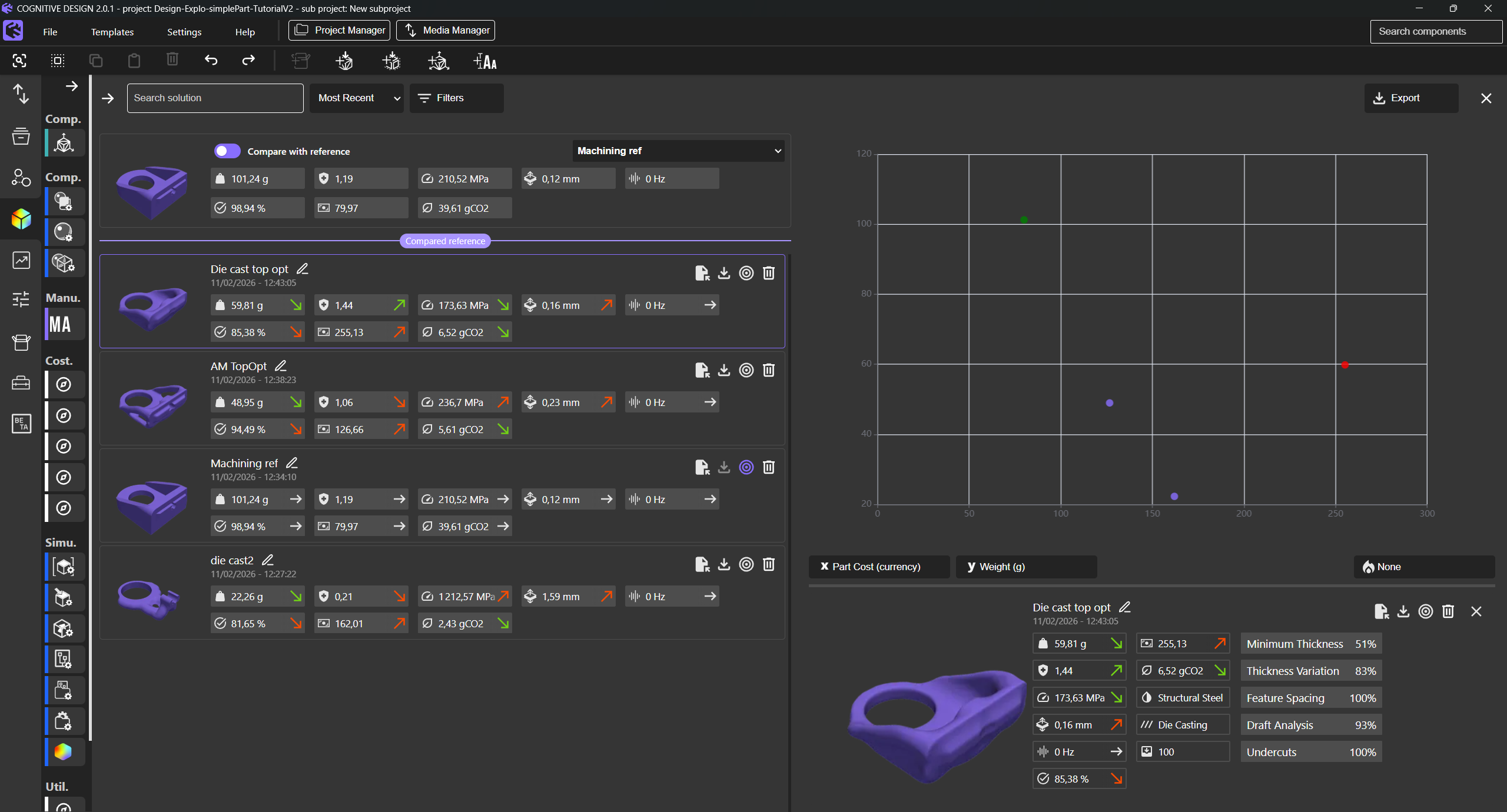
This pattern is common among large OEMs building additive manufacturing screening or portfolio evaluation processes. Identifying candidate parts fast requires comparing cost, CO2, and manufacturability across many options at once, not generating options faster in isolation. On an automotive upright program, this approach generated more than 100 design variants in parallel, each scored on the same criteria. A manual workflow would typically allow only 2 to 3 concepts.

The third context matters most where certification and auditability are non-negotiable. It only holds if the underlying computation runs on deterministic algorithms. The same inputs must always produce the same outputs, and every decision in the workflow stays traceable and reviewable.
This is a cross-cutting message, as relevant to engineering managers evaluating a tool for adoption as to the engineers using it day to day. Across defense contractors, regulated aerospace suppliers, and industrial Tier-1s, the same expectation holds: AI-assisted design tools need to be traceable, deployable on-premise, and kept human-in-the-loop. The Potez Aéronautique bracket program, evaluated against CS-25 aerospace certification requirements, ran on exactly this principle.
Turning a single expert's know-how into a shared engineering asset follows the same three-step principle in every team that has done it well. That principle is simple: build once, reuse instantly, share indefinitely. Build once means capturing a senior engineer's logic into a first parametric workflow for a recurring part family. Reuse instantly means validating that workflow on a second, truly different variant before treating it as production-ready. Share indefinitely means packaging the validated logic so any engineer on any team can import it without a handover meeting.
Start with identifying a recurring part family that already generates friction: a bracket type, a housing, a structural interface that shows up across multiple programs. Capture one senior engineer's logic into the first parametric workflow. Include the load cases, the manufacturing rules, and the validation thresholds they would normally apply from memory. This step takes the most time and the most senior judgment. It only needs to happen once per workflow class.
Validate the workflow on a second, genuinely different variant before declaring it production-ready. The goal at this stage is not speed. It is confirming that the class-level logic adapts to new geometry, rather than silently carrying over an invalid assumption. Once validated, measure the real time difference between the first part and the ones that follow. That comparison becomes the evidence base for the next investment decision.
Package the validated workflow so any engineer on any team can import it without a handover meeting. Consistency across the family becomes structural, not dependent on who remembers the right constraints. Every new program that touches a similar part family inherits the work, instead of starting from zero.
Explore our frequently asked questions to understand how our software can benefit you.
A CAD template stores geometry and default settings for one part type. A reusable engineering workflow stores the decision logic behind a family of parts: load cases, manufacturing constraints, and validation criteria. That logic adapts when the geometry changes, instead of requiring a manual rebuild for each variant.
Workflow amnesia is the systematic loss of engineering decision logic that occurs when a project ends, a team restructures, or a senior engineer leaves. It happens because legacy CAD and PLM systems version geometry and configuration, but never version the reasoning behind a design decision.
Results vary by program, but Thales Alenia Space's published case study documents subsequent variants dropping from 2 weeks to 2 days once a class-level workflow existed, a 7x acceleration, with a 50% cut in total lead time across the full 80+ variant family.
The configuration trap is the pattern of re-configuring a CAE setup from scratch for every part variant, despite consistent underlying engineering logic. Copy-pasting a previous configuration introduces silent constraint violations. A setup valid for a smaller aluminum part may not remain valid for a larger part in a different material.
No. A reusable workflow operates on top of existing CAD and PLM systems. It encodes the design logic and manufacturability rules as a portable asset, rather than replacing the geometry management and version control those systems already handle.
Generally no. The upfront investment in building a class-level workflow only pays back when a real family of similar parts follows. A truly unique part with no foreseeable variant is usually faster to configure directly.
Ownership typically sits with methods and tools teams, or with senior engineering leads who already define standards across programs. They have visibility into which part families recur across multiple projects and teams.
Part family reuse applies the same class-level logic to variants that already belong to a known family, cutting configuration time on each one. Design exploration uses the same logic to generate and score many candidate designs in parallel, which only proves worthwhile if a dedicated module compares the results automatically instead of by hand.
Payback depends on family size, but the pattern holds. The first part carries close to the full cost of the investment, and each subsequent variant costs a fraction of that, so payback typically arrives by the second or third variant in the family.

Request a demo to see how Cognitive Design by CDS can revolutionize your engineering workflow
.avif)

.avif)
.avif)
