.avif)
Rhushik Matroja
CEO
Last updated: July 2026
Topology optimization is a computational method that has been mathematically mature since the 1980s, extensively documented in both academic and industrial literature. Yet in most engineering departments, its raw output is still treated as a suggestion to be redrawn by hand rather than as a directly usable geometry. This gap between the maturity of the calculation and the immaturity of the industrial workflow around it explains why so many lightweighting projects run weeks longer than planned, and why so many engineers remain cautious about a technology whose potential has been demonstrated for decades. This guide explains what topology optimization actually is, where it creates value in aerospace, space, defense and automotive, and where it reaches its limits.
Topology optimization is a numerical method that determines the best distribution of material within a given design space, based on loads, boundary conditions and a performance objective such as stiffness or mass. Unlike manual design, it imposes no starting shape: the algorithm is left to derive an optimal load path from an initial design space, usually oversized to begin with.
Two broad families of methods coexist in current tools. The density-based approach, the most widely used, assigns each mesh element a value between 0 and 1 representing the presence or absence of material, then converges that value through successive iterations. The level-set approach represents the boundary between material and void as a continuous function that evolves at each iteration, which typically produces smoother contours in the output.
A common point of confusion is worth clearing up before going further. Topology optimization, shape optimization, parametric optimization and generative design do not refer to the same thing, even though these terms are frequently used interchangeably in technical conversations.
This distinction matters because the choice of method directly determines how much rework is needed before the result is a manufacturable part, a point developed further in this guide.
.gif)
In these four sectors, mass is never an isolated criterion: it directly drives operational cost, performance or payload capacity over a product's entire life. This is why these industries were among the first to adopt topology optimization as soon as it became accessible outside research labs, well before its wider adoption in sectors less sensitive to weight.
In commercial aviation, a commonly cited industry rule of thumb is that a 1% reduction in aircraft mass translates into roughly a 0.75% drop in fuel consumption over the aircraft's operational life. Multiplied by decades of operation and hundreds of onboard parts, this ratio explains why every gram saved on a fitting or a bracket is tracked closely in aerospace program budgets.
In space, the logic is even more direct: launch cost per kilogram remains one of the largest expense items in any launch program, which makes every gram saved on a secondary structure directly quantifiable in dollars.
Defense programs add a requirement that civil aerospace does not always face to the same degree: full traceability of the design process, required during qualification. A part produced through topology optimization must be able to demonstrate, step by step, how it was obtained and why it satisfies the mechanical requirements of the specification. Deploying design tools in a controlled environment, sometimes fully offline for security reasons, becomes a selection criterion in its own right.
In automotive, the dominant constraint is different: production scale is what changes the equation. An optimized part must remain compatible with high-volume processes such as die casting or stamping, while meeting crash and NVH (noise, vibration, harshness) requirements that do not exist in the same form in aerospace.
Across publicly documented industrial projects, observed mass reductions range from 30% on heavily loaded automotive parts to 60% on aerospace fittings redesigned without legacy geometry constraints, with a commonly cited median around 45% on families of structural brackets.
The traditional topology optimization workflow follows a well-established sequence: preparing a CAD model that represents the design space, meshing with finite elements, applying loads and boundary conditions, running the iterative solver to convergence, then interpreting the resulting density field.
It is the next step that has historically absorbed most of the friction. The raw output of a density-based optimization is a faceted surface, directly inherited from the mesh resolution, which generally cannot be sent to manufacturing as-is or easily reintegrated into a parametric CAD model. A clean geometry then has to be reconstructed, often by hand, using sculpting or reverse-engineering tools, before the reconstructed part can be mechanically revalidated.
This point deserves an honest trade-off rather than a promise of a silver-bullet fix. Manual reconstruction is not purely a technical constraint to eliminate: it also acts as a quality filter, where an experienced engineer corrects computational artifacts and applies engineering judgment. Automating this step, which is now possible with implicit geometries rather than meshes, does not remove the need for that control. It simply shifts when that control is applied, and how to preserve it inside a faster workflow remains a genuine methodological question.
This reconstruction and revalidation cycle is routinely cited by engineering teams as the single biggest source of delay in a lightweighting project, more so than the optimization calculation itself. On a significant aerospace or defense project, the total time between launching the study and reaching a validated first concept is generally measured in weeks rather than days.
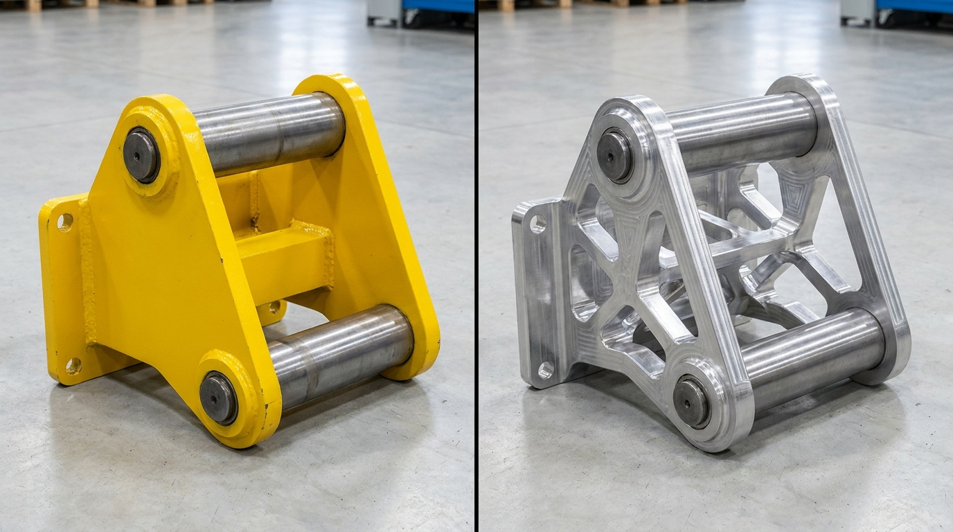
A methodological shift has been spreading across the sector over the past few years: instead of treating manufacturability as a check performed after optimization, several teams now build manufacturing constraints directly into the exploration phase itself. This is often referred to as manufacturing-driven design.
In practice, this means the optimization algorithm no longer searches purely for the best stiffness at a given mass. It explores the design space while accounting from the outset for draft angles compatible with a mold, overhang angles compatible with an additive manufacturing build orientation, or tool accessibility required for machining. The result is a geometry that remains mechanically efficient while staying manufacturable without heavy reconstruction.
.jpg)
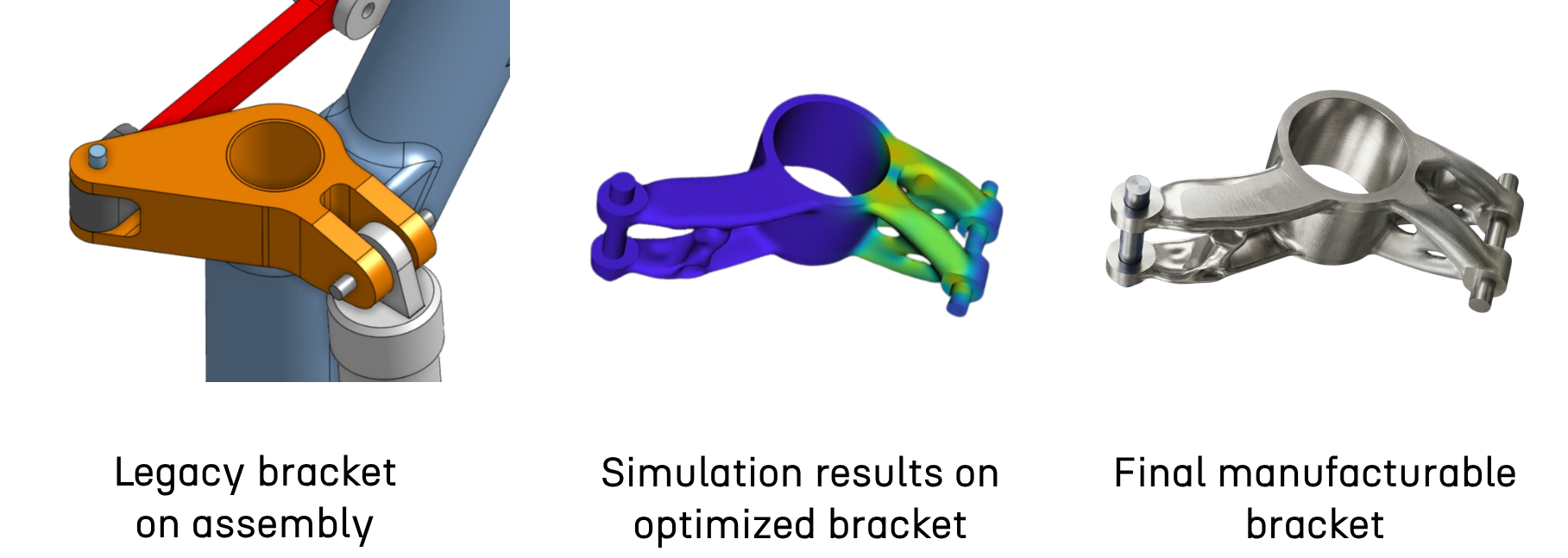
A documented aerospace example illustrates this logic concretely on a landing gear actuation bracket. Rather than running a single sequential optimization, the team ran two optimization routes in parallel from the same load environment, producing two genuinely different geometric families to compare on mass, stress and manufacturability. The selected concept achieved a 60% mass reduction, from 1.4 kg to 0.56 kg, with peak stress brought down to 294 MPa against 270 MPa on the original part, just 9% above baseline despite the weight loss. Engineering lead time to reach a first concept dropped from an estimated 8-10 weeks to 1-2 weeks, a reduction of roughly 85%. See the full case study.
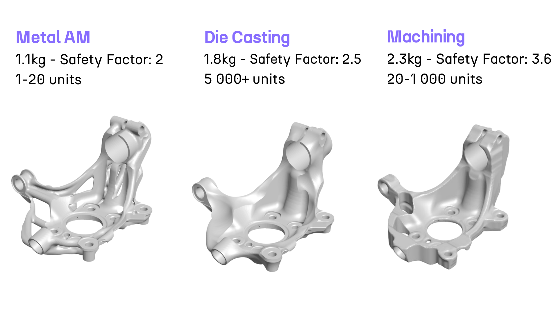
A project on an automotive suspension upright confirms that this approach is not limited to one sector or one manufacturing process. Starting from a steel part judged to be over-engineered but hard to improve with conventional tools, the team generated and compared more than 100 variants across three distinct processes (additive manufacturing, CNC machining and die casting) within a single exploration workflow. The final part, redesigned in Ti-6Al-4V, achieved a 30% mass reduction (from 3.20 kg to 2.24 kg), and engineering time for the full exploration dropped from 96 to 4 hours. See the full case study.
Not all manufacturing constraints carry equal weight in shaping a topology optimization outcome. Three process families dominate current usage across aerospace, space, defense and automotive, each with its own geometric rules.
Ignoring these constraints during the exploration phase does not invalidate the optimization, but it pushes the problem further down the development cycle, to a point where fixing it costs considerably more than it would have at the design stage. This time lag between discovering a manufacturability issue and correcting it is precisely what makes it one of the costliest friction points in lightweighting projects.
A geometry produced by topology optimization is never treated as final before being mechanically revalidated, typically through a new finite element analysis applied directly to the reworked geometry.
The classic friction point at this stage comes down to meshing. Every geometric change, however minor, in theory requires a new mesh before a calculation can be rerun, which significantly slows the iteration loop between design and validation.
A frequent trap is accepting the lightest result outright without checking what it costs in safety margin. On the landing gear bracket cited earlier, the first optimization pass did reach a 60% mass reduction, but it also pushed peak Von Mises stress from 270 to 426 MPa, a level incompatible with the specification. Rather than discarding the concept or accepting that stress level, the team used targeted structural analysis to add material back only where it was actually needed, bringing the peak down to 294 MPa while preserving nearly all of the original mass reduction.
This kind of fast iteration between calculation and geometric change is what made it possible, on this project, to compare two families of solutions and then fine-tune the reinforcement, rather than having to choose between the lightest concept and the safest one. Simulation approaches that avoid remeshing at every change, working directly on an implicit representation of the geometry, are starting to become more common in recent tools to shorten this kind of loop.
Stiffness and mass remain the historical objectives of topology optimization, but they are no longer sufficient on their own to judge a design's relevance in a real industrial context. Three other indicators are taking on a growing role in recent projects.
In regulated sectors such as defense and aerospace, a fourth indicator matters: design traceability, meaning the ability to document every decision and every iteration to satisfy qualification requirements, a need that becomes more structural as optimization processes grow more complex.
Topology optimization does not add value in every situation, and acknowledging that explicitly is part of taking the subject seriously.
On very low part volumes, the time needed to set up and validate a full optimization can exceed the actual gain, particularly if the part represents only a marginal fraction of the system's total mass. Standardized interfaces, where design freedom is limited by interoperability standards, also leave the algorithm little room to work with, regardless of how sophisticated the tool is.
In strict qualification contexts, a highly organic geometry can also complicate comparison with an already-certified reference part, sometimes extending qualification timelines more than the mass gain justifies. In these cases, a more conservative shape optimization, applied to an existing geometry rather than a blank design space, often remains the more pragmatic choice.
Topology optimization remains a tool, not an end in itself. Its value depends directly on how well it integrates into a broader design workflow, including manufacturability, mechanical validation and the traceability each sector requires. Two concrete examples show this logic applied to real cases: the lightweighting of an automotive upright and of a landing gear bracket, both carried out in 2026 using the same manufacturing-driven design approach described in this guide.
Explore our frequently asked questions to understand how our software can benefit you.
Topology optimization searches for the best material distribution for a given objective within a fixed design space. Generative design is a broader process that can explore multiple objectives, materials and manufacturing processes in parallel, with topology optimization as just one building block of that process.
Across publicly documented industrial projects, mass reductions range from 30% on heavily loaded automotive parts to 60% on aerospace parts redesigned without legacy geometry constraints, with significant variation depending on the starting geometry and specification constraints.
The calculation itself typically takes anywhere from a few minutes to a few hours depending on model complexity. It is the reconstruction and revalidation phase that really determines the total project duration. On one documented aerospace case, the time to a validated first concept dropped from an estimated 8-10 weeks to 1-2 weeks through parallel rather than sequential exploration.
No. The lightest result is not always the one with the best safety margin. A more robust practice is to compare several concepts generated in parallel, then locally reinforce the selected geometry only where structural analysis shows a genuine need, rather than accepting the lightest solution outright or rejecting it altogether.
Yes, provided the design process is documented and traceable, and the final geometry is revalidated using the qualification methods applicable to the relevant sector. The complexity usually lies less in the calculation itself than in the compliance documentation that accompanies it.
It is a validation approach that works directly on an implicit representation of the geometry rather than a discretized mesh, which avoids remeshing at every iteration and significantly speeds up design loops.

Request a demo to see how Cognitive Design by CDS can revolutionize your engineering workflow
.avif)